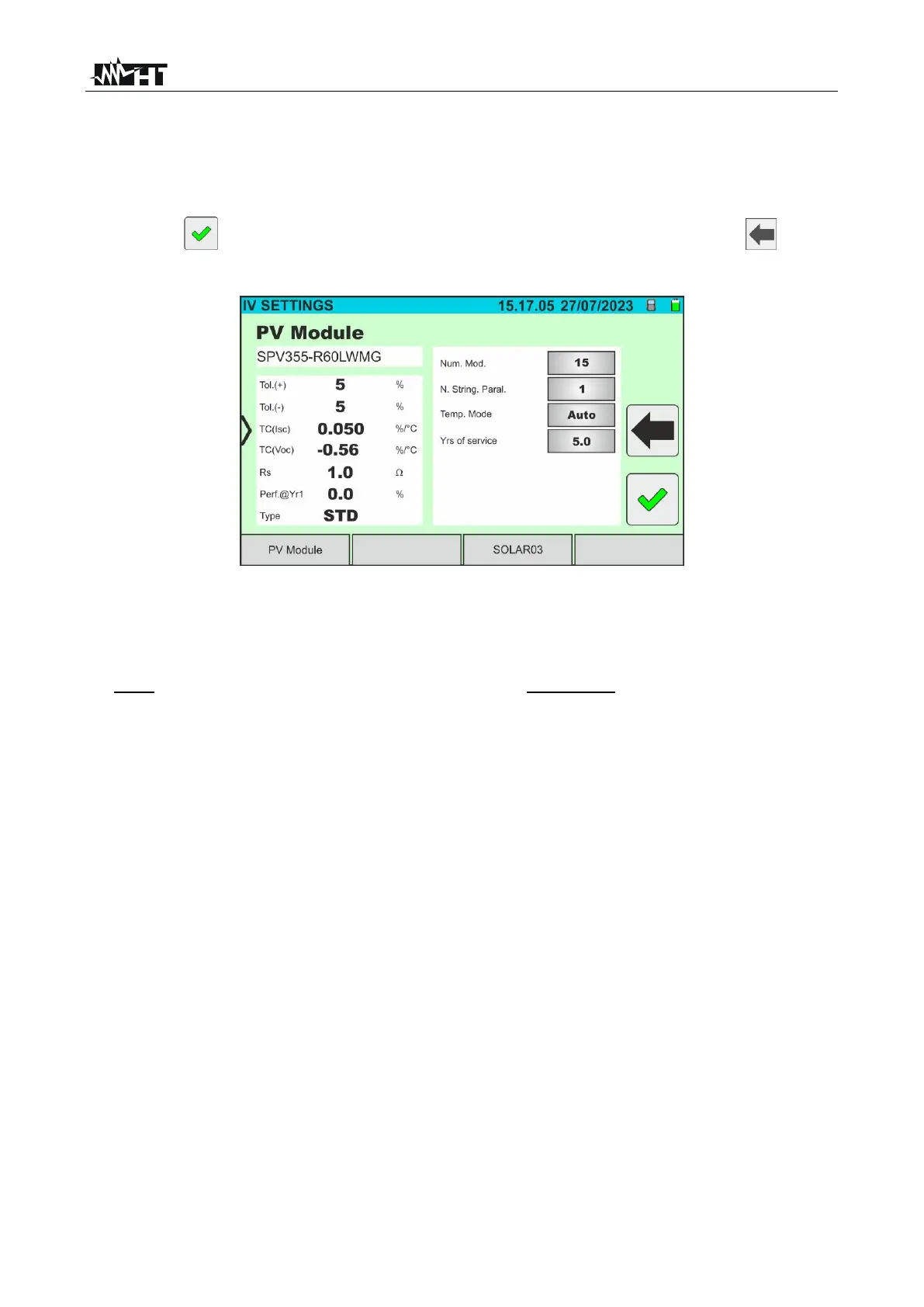
6. Tap on the "Settings” key (Monofacial module reference). The following screen is
shown in Fig. 36. The following parameters are given:
➢ References of the currently selected module
➢ Parameters of the test string to be programmed
➢ Icon to save the settings and return to the main screen, or icon to exit
without saving
Fig. 36: I-V curve measurement parameter settings
7. Tap on the "PV Module” key to change the PV module to be tested. The instrument
opens the DB section, where a new module can be selected from the list in the DB
section (see § 6.3)
3. Drag each of the 4 available thumb wheels to the right or left to set the desired value of
the following parameters:
➢ Num. Mod → to set the number of modules in the string being tested (max. 35)
➢ N. String Paral. → to set the number of strings in parallel (max. 5). Setting "1”
indicates the presence of only one overall string
➢ Temp. Mode → to set the module temperature measurement mode. The following
options are available: Auto (temperature calculated by the instrument based on the
Voc measurement and the nominal parameters of the module- no probe
connected and recommended option), Meas. (temperature measured via PT305
probe connected to the SOLAR03 remote unit)
➢ Yrs of service (setting the number of years of operation of the PV system being
tested in the range 0.1 ÷ 49.9 years with 0.1-year increments), considering that 0.5
years = 6 months. This information is used by the instrument to determine the I-V
curve
8. Tap on the "SOLAR03” key to access the control and management section of the
SOLAR03 remote unit (see § 6.2). Check that the remote unit is active and connected
to the instrument
9. Check that the value set in the “Min. Irradiance” section (see § 5.2) is consistent with
the measurements to be taken. It is recommended to measure with a threshold of
700 W/m
2
in accordance with the IEC/EN60891 standard.