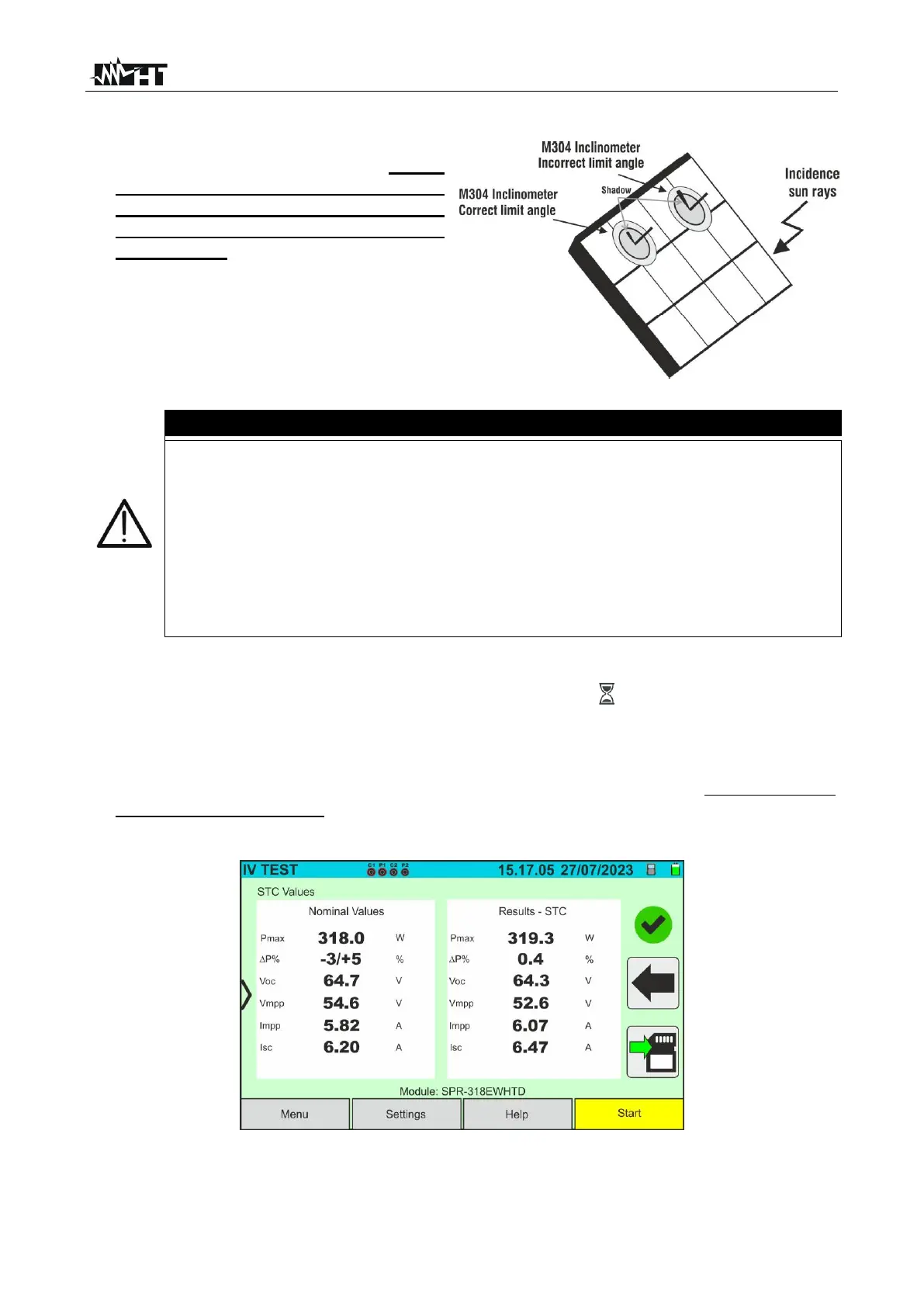
10. Assemble the stem onto the disk of the
optional accessory M304 and keep it
resting on the module’s surface. Check
that the shadow of the stem on the
disk falls within the internal “limit
concentric circle” of the disk itself
(see picture). If this is not the case, the
angle between the sun's rays and the
module surface is too high and
therefore the measurements taken by
the instrument are NOT reliable.
Repeat the operations at other times
of the day
• When START/STOP (or Start on the display) is pressed, the instrument may
give various error messages (see § 6.4.5) and, as a result, fail to perform the
test. Check and, if possible, eliminate the cause of the problem before
proceeding.
• The method used by the instrument meter for output VDC and IDC
measurements of PV module/string is the “4-wire”. Therefore, it is possible to
use also test cables connected to P1, C1, P2, C2 inputs of different length
without performing any calibration of cable resistance. For extensions, only
use accessories supplied by HT
11. Press the START/STOP key (or Start on the display) to activate the test. If there are
no error conditions, the instrument will show the icon " on the display for a few
moments together with the message "Measuring..." The test can take up to
approximately 20 seconds, depending on the open circuit voltage and module
parameters. At the end of the test, the values related to the @STC conditions, and
the corresponding result are displayed (here below, for convenience, only Monofacial
modules are referred to (the results for bifacial modules are similar as they refer to the
equivalent front-side Irradiance
Fig. 37: Example of I-V curve measurement result - STC values
12. The measurement result screen shows the following parameters: