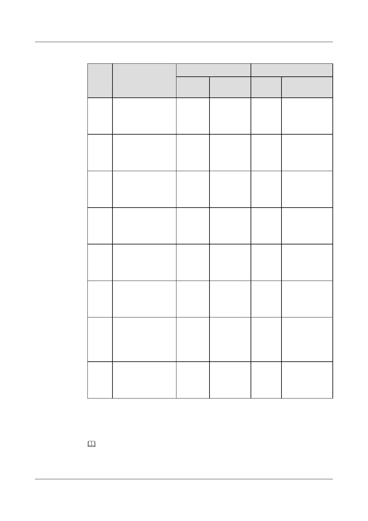
Table 7-2 Signal cables installed in the BTS3900A (AC) cabinet
No. Cable One End The Other End
Connect
or
Installation
Position
Connec
tor
Installation
Position
S1 Environment
monitoring signal
cable
DB50
male
connector
PMU/COM DB50
male
connecto
r
Fan box in the
APM30H/
HPMI/
PMU_DB50
S2 Monitoring signal
transfer cable
RJ-45
connector
PMU/
COM_IN
RJ-45
connecto
r
Fan box in the
APM30H/
CMUA/
COM_OUT
S3 Monitoring signal
cable between the
BBU and the CMUA
in the APM30H
RJ-45
connector
CMUA/
COM_IN
RJ-45
connecto
r
BBU/UPEU/
MON1
S4 Monitoring signal
cable between the
BBU and the CMUA
in the RFC
RJ-45
connector
CMUA/
COM_IN
RJ-45
connecto
r
BBU/UPEU/
MON0
S5 Temperature
monitoring signal
cable for the RFC
4-pin
connector
Fan box in
the RFC/
CMUA/
TEM
Tempera
ture
sensor
Air inlet at the
bottom of the
RFC
S6 Signal cable for the
ELU
RJ-45
connector
ELU RJ-45
connecto
r
Fan box in the
APM30H or in
the RFC/CMUA/
ELU
S7 Monitoring signal
cable for the door
status sensor in the
APM30H
2-pin
connector
Fan box in
the
APM30H/
HPMI/
GATE
Bare
wire
Door status
sensor in the
APM30H
S8 Monitoring signal
cable for the door
status sensor
Cord end
terminal
Fan box in
the RFC/
CMUA/
GATE
Bare
wire
Door status
sensor in the
RFC
Check whether the transmission cables are correctly and securely installed in the cabinet by
referring to Table 7-3.
NOTE
For the transmission cable routing in various RATs and transmission modes, see section Transmission
Cable Connections in the BTS3900A (Ver.B) Hardware Description.
BTS3900A(Ver.B)
Installation Guide 7 Checking the Installed Cables and Modules
Issue 01 (2011-10-25) Huawei Proprietary and Confidential
Copyright © Huawei Technologies Co., Ltd.
29