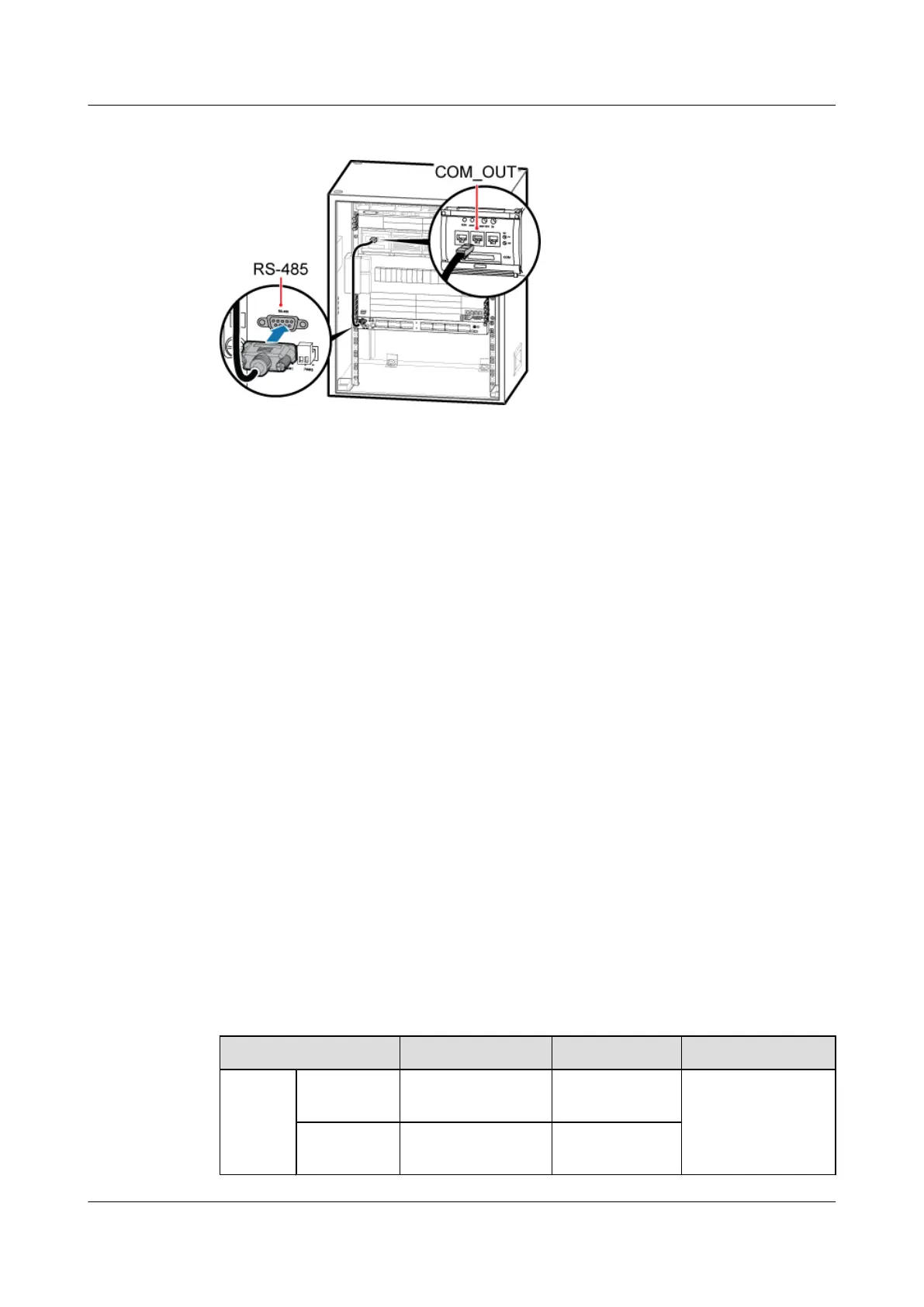
Figure 11-10 Installing the EMUA monitoring signal cable
1. Connect the DB9 male connector at one end of the signal cable to the wiring terminal labeled
RS-485 in left of the EMUA panel.
2. Connect the RJ45 connector at the other end of the signal cable to COM_OUT of the PMU
in the cabinet.
Step 4 Route the cables by referring to 12.1 Cabling Requirements and use cable ties to bind the
cables.
Step 5 Attach labels to the installed power cable and monitoring signal cable. For details, see Attaching
a Sign Plate Label and Attaching an L-Shaped Label.
----End
11.2.2 Installing the EMUA in the TMC11H
This section describes the installation of the EMUA when the TMC11H is used and the cable
connection between the EMUA and the external devices. The EMUA can be installed in the
reserved space of the 1 U-high TMC11H cabinet.
Prerequisite
The tools such as the screwdriver and ESD gloves are available.
Context
Table 11-4 describes the cables related to the EMUA.
Table 11-4 Cables related to the EMUA
Cable List
One End The Other End Remarks
Power
cable for
the
EMUA
RTN(+)
cable
M4 OT terminal Cord end
terminal
Black, 1.5 mm
2
, two
wires in black and
blue
NEG(-) cable M4 OT terminal Cord end
terminal
BTS3900A(Ver.B)
Installation Guide 11 Installing Optional Modules
Issue 01 (2011-10-25) Huawei Proprietary and Confidential
Copyright © Huawei Technologies Co., Ltd.
64