NOTE
l If the CPRI cable is redundant, coil and tie the extra length of the cable on the top of the DCDU-01 in the
RFC cabinet or in the base.
l Route the cable in strict compliance with Figure 12-64. The CPRI cable must be routed to the cable rack in
the middle of the RFC before it is routed to the RFU.
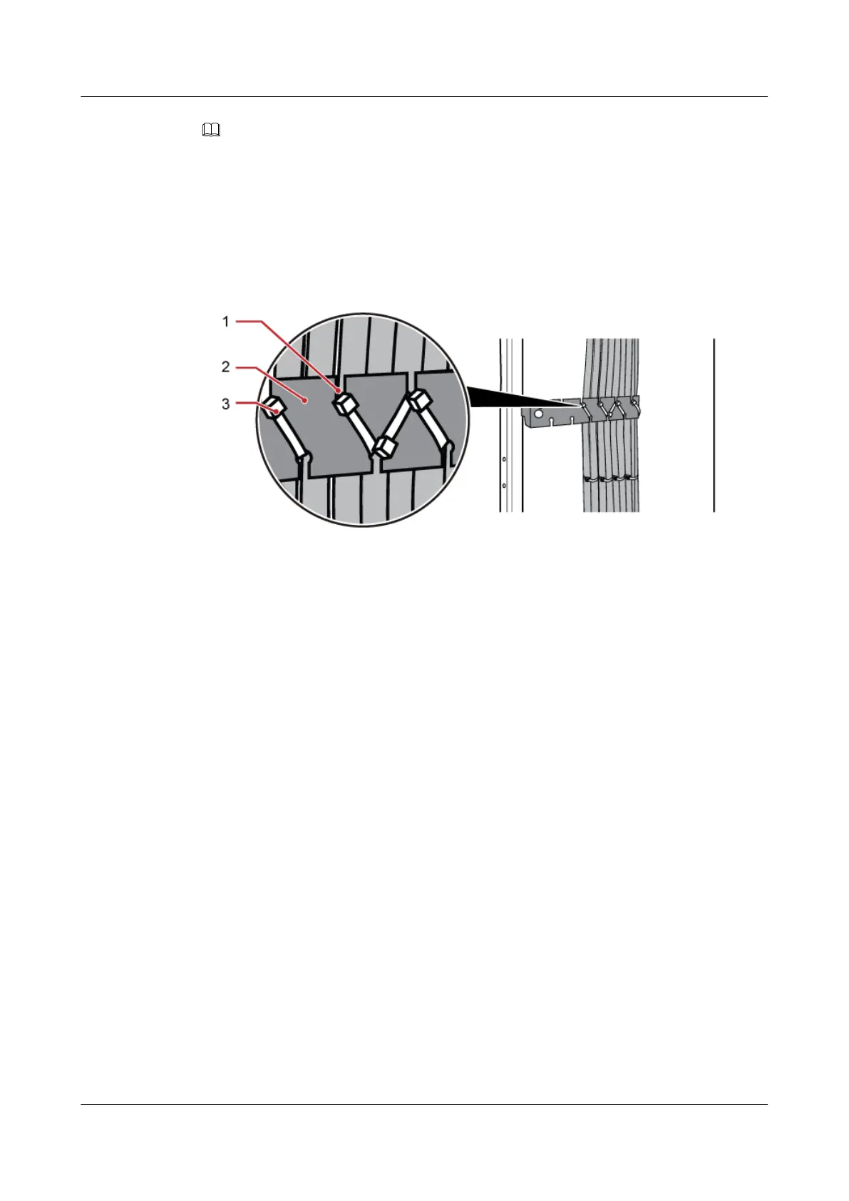
l Bind the cable during the cable routing. Tie the cable on the binding bracket by leading the cable tie through
the cable and upper and lower cabling teeth. Ensure that the heads of all the cable ties are outside the cabling
teeth, as shown in Figure 12-65.
Figure 12-65 Binding CPRI cables
(1) Cabling teeth (2) Binding bracket (3) Cable tie
Step 6 Attach labels to the installed cables. For details, see Attaching an L-Shaped Label.
----End
12.8 (Optional) Installing Inter-BBU Signal Cable
Install inter-BBU signal cable with a DLC connector at both ends for interconnecting optical
ports onsite when a triple-mode base station is configured as GU (BBU0)+L(G) (BBU1) or GL
(BBU0)+U(G) (BBU1).
Context
A 10 m inter-BBU signal cable is recommended.
Procedure
Step 1 Install the inter-BBU signal cable on the BBU0 side, For details, see Installing Optical Modules
and Cables.
1. Install an optical module to the port M0 on the universal inter-connection infrastructure
unit (UCIU) on BBU0.
2. Insert the DLC connector at the end labeled 2A and 2B on the cable into the optical module.
Step 2 Route the cable through the cable hole on the right of the power cabinet, through the cable hole
on the left of the RF cabinet, and then to the BBU1 in the extension power cabinet, as shown in
Figure 12-66 and 12.1 Cabling Requirements.
BTS3900A(Ver.B)
Installation Guide 12 Installing the Cables
Issue 01 (2011-10-25) Huawei Proprietary and Confidential
Copyright © Huawei Technologies Co., Ltd.
145