Step 3 Route the other end of the CPRI cable out of the cabinet along the RF cable through the cable
hole on the left of the power cabinet, and then route the CPRI cable into the RF cabinet. Then,
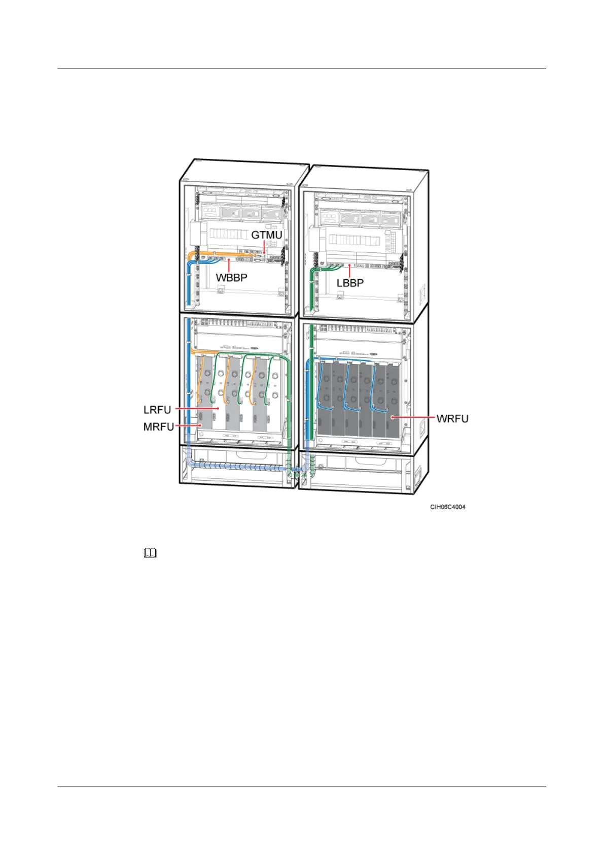
route the CPRI cable to the corresponding RFU, as shown in Figure 12-64.
Figure 12-64 Installation of the CPRI cable
NOTE
As shown in Figure 1, the lines in yellow are cables already installed before delivery, and the lines in blue
and green are cables that need to be installed on site.
Step 4 Insert the SFP connector at the other end of the CPRI cable into the CPRI0 port on the RFU
panel, as shown in Figure 12-64.
Step 5 Route the cables by referring to 12.1 Cabling Requirements and use cable ties to bind the
cables.
BTS3900A(Ver.B)
Installation Guide 12 Installing the Cables
Issue 01 (2011-10-25) Huawei Proprietary and Confidential
Copyright © Huawei Technologies Co., Ltd.
144