Step 3 Lead the other end of the FE/GE cable out of the cabinet through the cable hole at the bottom
along the right of the cabinet.
Step 4 Route the cable along the right of the cabinet by referring to 12.1 Cabling Requirements, and
then use cable ties to bind the cable.
Step 5 Label the installed cables by referring to Attaching an L-Shaped Label.
----End
12.4.3 Installing the FE/GE Optical Cable
This section describes the procedure and precautions to be taken for installing an FE/GE optical
cable.
Context
l The single-mode optical module is labeled "SM" and multi-mode optical module is labeled
"MM".
l If the puller of an optical module is blue, the module is a single-mode optical module. If
the puller of an optical module is black or grey, the module is a multi-mode optical module.
NOTE
The procedures for installing FE/GE optical cables in an APM30H and in an TMC11H are the same. The
following description is based on the procedure for installing an FE/GE optical cable in an APM30H.
CAUTION
The performance of an optical module that is exposed to the air for more than 20 minutes may
be abnormal. Therefore, you must insert an fiber optic cable into an unpacked optical module
within 20 minutes.
Procedure
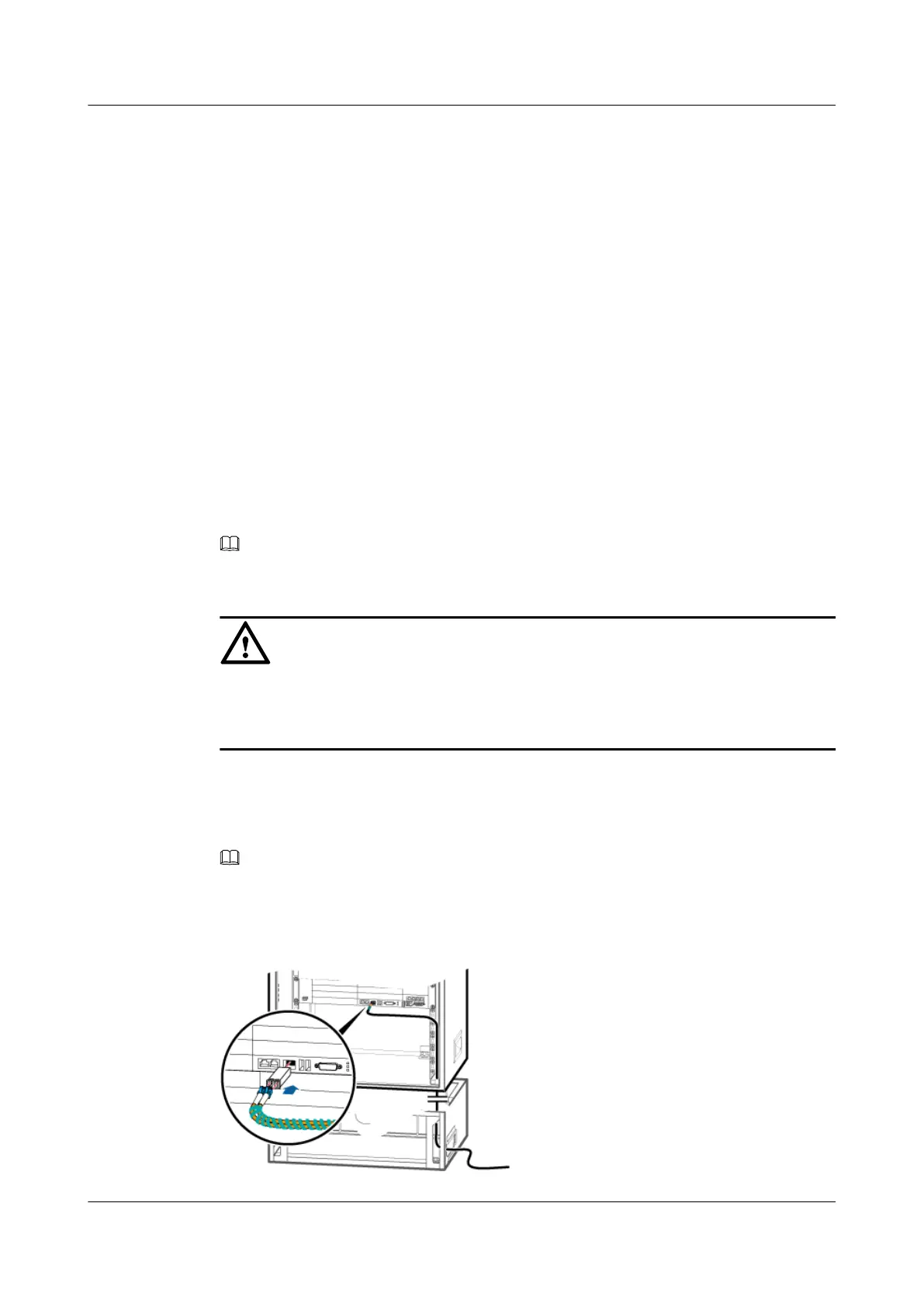
Step 1 Insert an optical module into the corresponding FE/GE optical port, as shown in Figure
12-29.
NOTE
For details about how to connect the FE/GE optical cable, see Transmission Cable Connections.
Step 2 Insert one end of the FE/GE optical cable into the optical module, as shown in Figure 12-29.
Figure 12-29 Installing the FE/GE optical cable
BTS3900A(Ver.B)
Installation Guide 12 Installing the Cables
Issue 01 (2011-10-25) Huawei Proprietary and Confidential
Copyright © Huawei Technologies Co., Ltd.
114