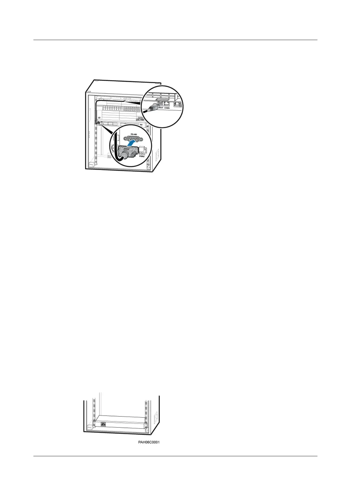
Step 3 Figure 11-13 shows the connection of the EMUA monitoring signal cable.
Figure 11-13 Installing the EMUA monitoring signal cable
1. Connect the DB9 male connector at one end of the signal cable to the wiring terminal labeled
RS-485 in left of the EMUA panel.
2. Connect the RJ-45 connector at the other end of the signal cable to COM OUT of the
CMUA in the cabinet.
Step 4 Route the cables by referring to 12.1 Cabling Requirements and use cable ties to bind the
cables.
Step 5 Attach labels to the installed power cable and monitoring signal cable. For details, see Attaching
a Sign Plate Label and Attaching an L-Shaped Label.
----End
11.3 (Optional) Installing a AC Heater
This section describes the procedures for installing a heater and related cables in a TMC11H.
Heaters may be required in a TMC11H based on actual requirements.
Context
If an SOU is not installed in the cabinet, an AC heater is preferentially installed in the bottom 1
U space of the cabinet, as shown in Figure 11-14. If an SOU is installed in the cabinet, an AC
heater must be installed above the SOU, as shown in Figure 11-15.
Figure 11-14 Position for installing an AC heater (1)
BTS3900A(Ver.B)
Installation Guide 11 Installing Optional Modules
Issue 01 (2011-10-25) Huawei Proprietary and Confidential
Copyright © Huawei Technologies Co., Ltd.
66