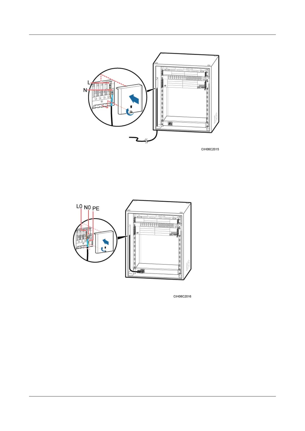
Figure 11-17 Installing the power cable for the junction box in the TMC11H
3. Respectively connect the OT terminals on the brown, blue, and yellow and green wires at
one end of the power cable for the heater to the L0, N0, and PE wiring terminals in the
junction box.
4. Link the C13 connector at the other end to the power supply socket on the heater.
Figure 11-18 Installing a power cable for the AC heater
Step 3 Route and bind the cables. For details, see 12.1 Cabling Requirements.
Step 4 Label the installed cables. For details, see Attaching a Cable-Tying Label.
----End
11.4 (Optional) Installing the GPS Surge Protector
This section describes the procedure and precautions for installing the GPS surge protector and
related cables.
BTS3900A(Ver.B)
Installation Guide 11 Installing Optional Modules
Issue 01 (2011-10-25) Huawei Proprietary and Confidential
Copyright © Huawei Technologies Co., Ltd.
68