Context
l The shielded straight-through FE/GE cable is the only qualified type of FE/GE cable.
l The FE/GE cable transmits baseband signals between a BBU and transmission equipment.
For the connections of FE/GE Ethernet cables, see the section about transmission cable
connections in the Hardware Description of each product.
Procedure
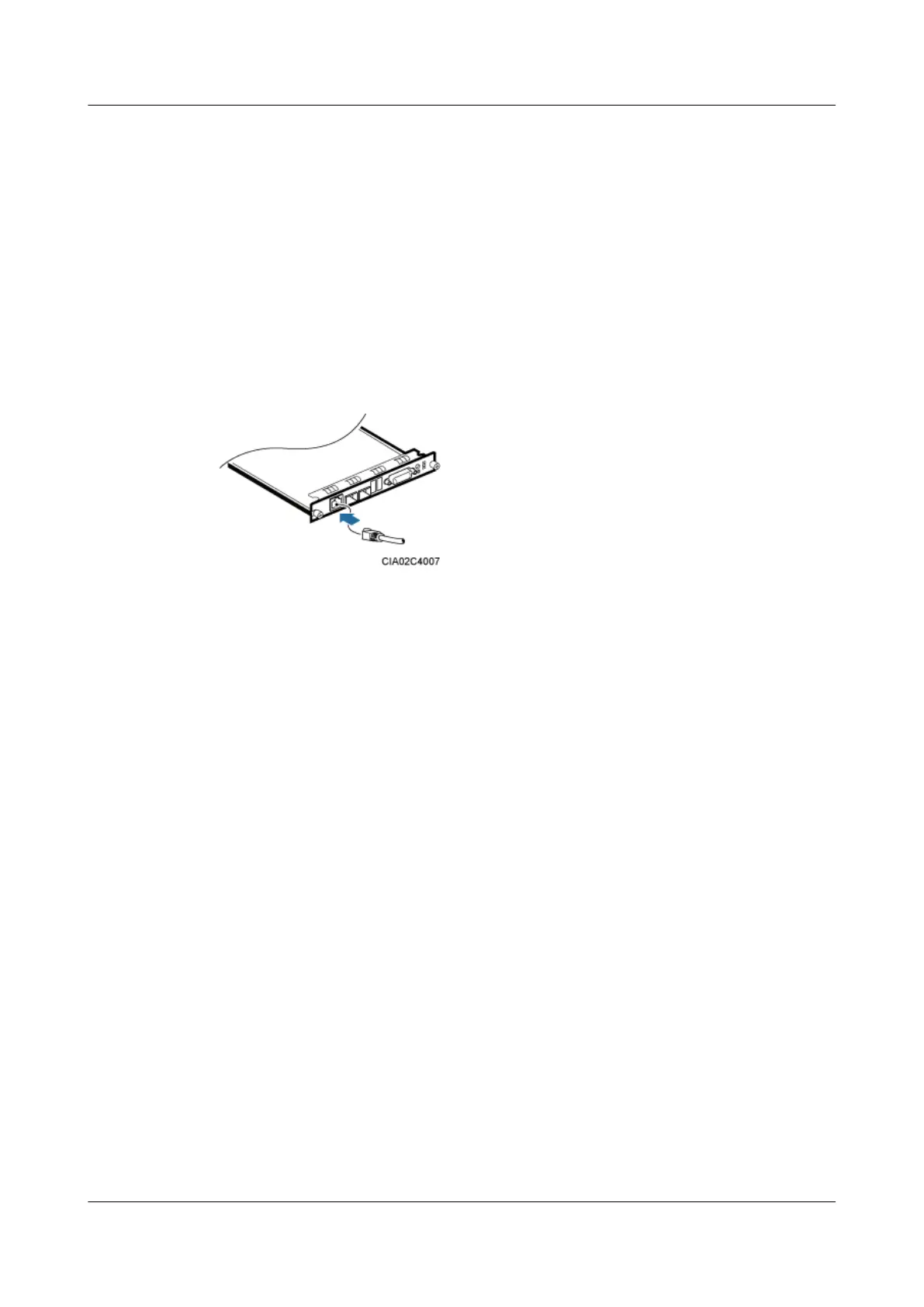
Step 1 Connect one end of an FE/GE cable to the FE0 port on the GTMU, WMPT, LMPT, UMPT, or
UTRP, as shown in Figure 11-30.
Figure 11-30 Installing the FE/GE cable
Step 2 Route the other end of the FE/GE cable out of the cabinet from a cable outlet.
Step 3 Route the cable along either side of the cabinet by referring to 11.1 Cabling Requirements, and
then use cable ties to bind the cable.
Step 4 Label the installed cables by referring to Attaching an L-Shaped Label.
----End
11.7 Installing the Monitoring Signal Cables
This section describes the procedure for installing monitoring signal cables and provides
important notes about the installation.
11.7.1 (Optional) Installing the Inter-BBU Signal Cable
This section describes the procedure for installing inter-BBU signal cables for a base station.
Prerequisites
l A new BBU has been added.
l Optical modules and fiber optic cables meeting the following requirements are available:
– The optical modules and fiber optic cables are of the multimode type.
– The multimode optical modules to be installed on the UMPT and UCIU support the
rates of 5 Gbit/s and 2.5 Gbit/s.
BTS3900L (Ver.C)
Installation Guide
11 Installing the Cables
Issue 07 (2013-11-08) Huawei Proprietary and Confidential
Copyright © Huawei Technologies Co., Ltd.
90