Step 4 Connect connectors at the other end of the RRU power cables to the correct ports and use a
screwdriver to tighten them, as shown in Figure 11-25.
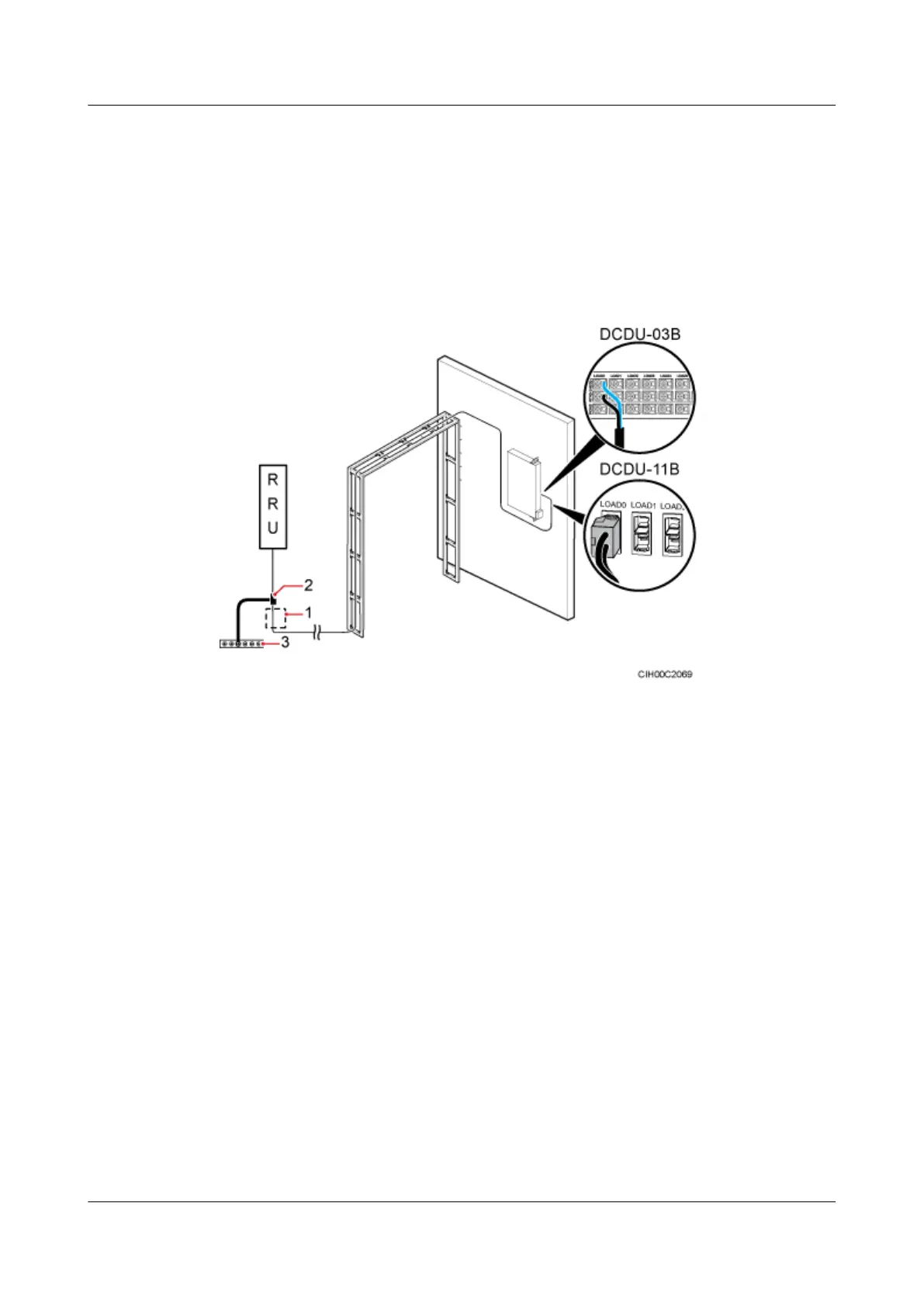
l For a BTS3900 (Ver.B) or BTS3900L (Ver.B), the OT terminals are connected to the LOAD0
to LOAD5 terminals on the DCDU-03B.
l For a BTS3900 (Ver.C) or BTS3900L (Ver.C), the tool-less female connectors (pressfit type)
are connected to the LOAD0 to LOAD5 ports on the DCDU-11B.
Figure 11-25 Installing the RRU power cables
(1) Feeder window (2) Ground clip (3) External ground bar
Step 5 Lay out the cables according to the instructions in Cabling Requirements, and use cable ties to
bind them.
Step 6 Label the installed cables according to the instructions in Attaching a Sign Plate Label.
----End
11.6 Installing the Transmission Cables
The E1/T1 cable or FE/GE cable can be used for data transmission according to the transmission
mode of the base station. Only one transmission mode can be supported by the base station
working in the GSM standard, and two transmission modes can be supported by the base station
working in the UMTS standard.
11.6.1 Installing an E1/T1 Cable
An E1/T1 cable transmits E1/T1 signals between the BBU and transmission equipment.
BTS3900L (Ver.C)
Installation Guide
11 Installing the Cables
Issue 07 (2013-11-08) Huawei Proprietary and Confidential
Copyright © Huawei Technologies Co., Ltd.
86