Figure 10-5 Installing the GPS jumper
Step 7 Route the cable by referring to 11.1 Cabling Requirements and Cable Routes.
Step 8 Attach labels to the installed cables. For details, see Labeling Signal Cables.
----End
10.2 Installing the GATM and Bias-Tee
This describes the procedures and precautions for the installation of the GATM and Bias-Tee
when they are used together with the DRFU.
Context
The Bias-Tee couples the DC power or OOK signals into the feeder. The GATM is connected
to the antenna through the Bias-Tee. If the DRFU is configured, the GATM and Bias-Tee must
be configured.
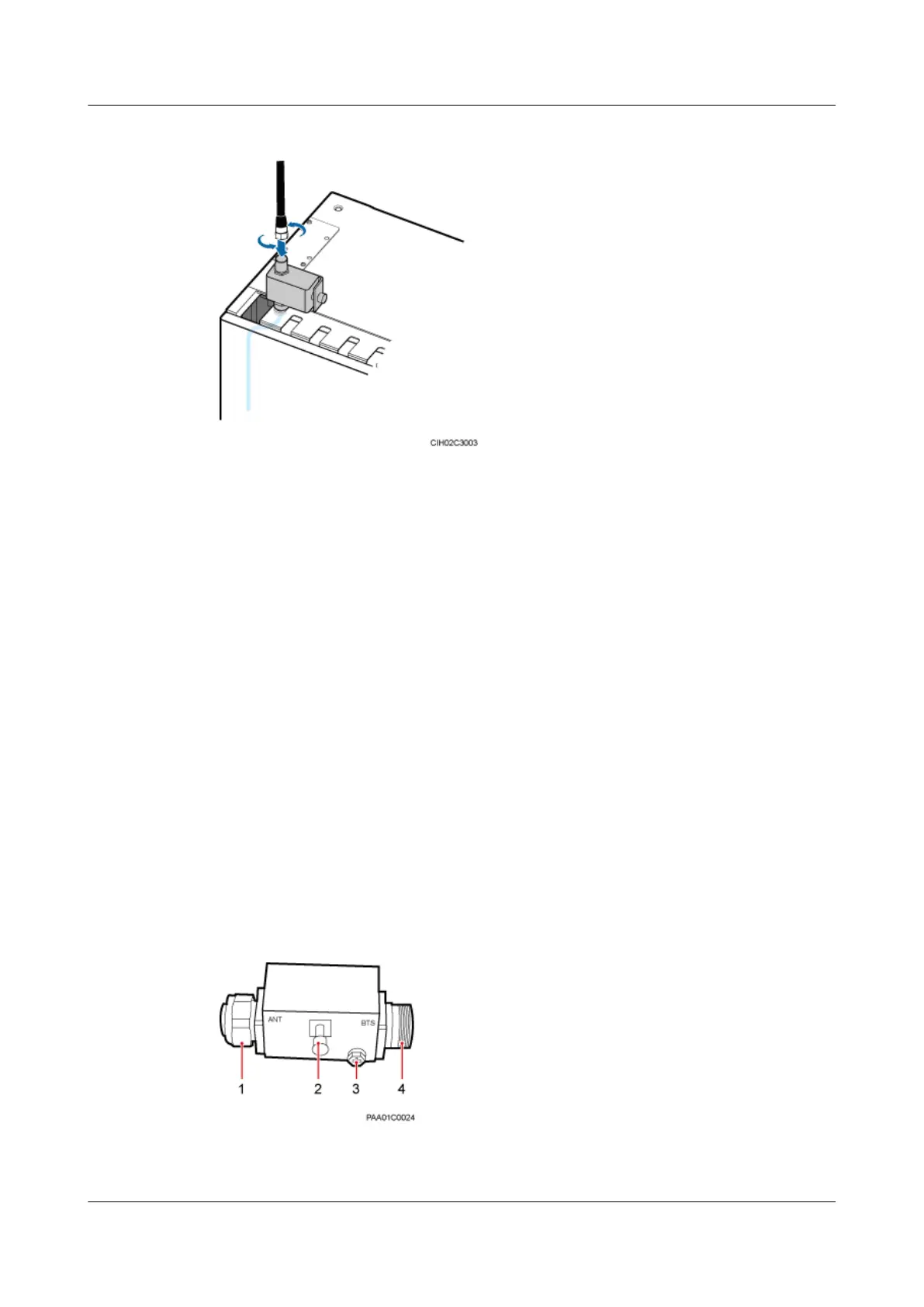
Figure 10-6 shows the cable connection ports of the straight DIN Bias-Tee. Table 10-1 describes
the cable connection of the straight DIN Bias-Tee.
Figure 10-6 Cable connection ports of the straight DIN Bias-Tee
BTS3900L (Ver.C)
Installation Guide
10 (Optional) Installing the Modules
Issue 07 (2013-11-08) Huawei Proprietary and Confidential
Copyright © Huawei Technologies Co., Ltd.
49