Figure 11-28 Installing the optical module
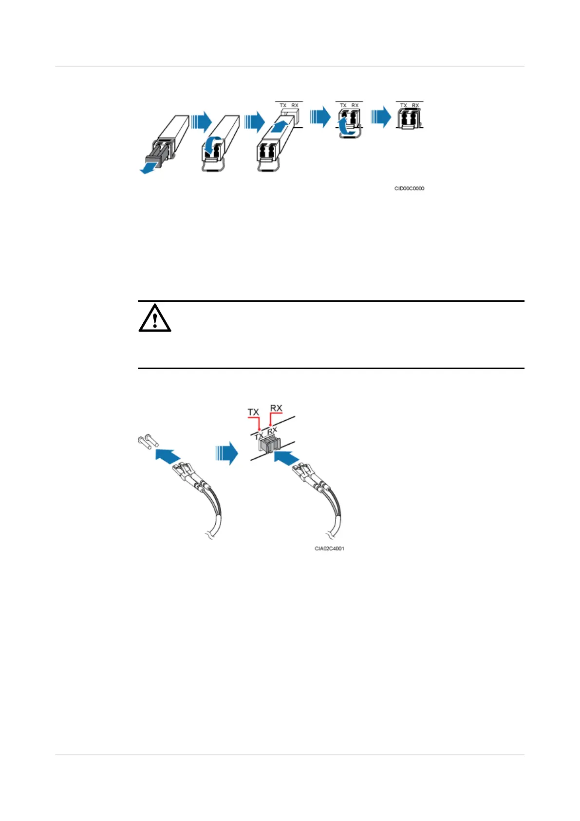
Step 2 Install the fiber optic cable, as shown in Figure 11-29.
1. Remove the dustproof cap from the connector at the end labeled 2A and 2B on the fiber
optic cable, and insert the connector into the optical module on the BBU.
2. Route the fiber optic cable out of the cable outlet on the bottom right side of the cabinet.
3. Connect the other end of the fiber optic cable to a routing device.
NOTICE
The TX and RX ports on the BBU boards must be connected to the RX and TX ports on the
transmission equipment, respectively.
Figure 11-29 Routing the FE/GE optical cable
Step 3 Lay out the cables according to the instructions in Cabling Requirements. If a fiber optic patch
cord is used as a BBU interconnection signal cable, use binding straps to bind the BBU
interconnection signal cable before using cable ties to secure it. If another type of cable is used
as a BBU interconnection signal cable, directly use cable ties to secure it.
Step 4 Label the installed cables according to the instructions in Attaching an L-Shaped Label.
----End
11.6.3 Installing an FE/GE Cable
This section describes the procedure and precautions to be taken for installing an FE/GE cable.
BTS3900L (Ver.C)
Installation Guide
11 Installing the Cables
Issue 07 (2013-11-08) Huawei Proprietary and Confidential
Copyright © Huawei Technologies Co., Ltd.
89