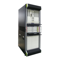
Power Module Mappings
The NE40E-X16A supports multiple power supply scenarios, which vary in the installed
PEMs and PMs. Table 1-73 lists the mappings between power supply scenarios and
PEMs/PMs.
Table 1-73 Mappings between power supply scenarios and PEMs/PMs on the NE40E-X16A
-48 V DC power supply system supports N+1 (1 indicates the number of backup modules)
PMs power module backup. The AC, 240 V HVDC, and 380 V HVDC power supply systems
supports N+N (N indicates the number of working modules)PMs power module backup. The
power supply system supports the backup of power supply areas A and B on the user side,
ensuring that the entire system can work properly if any power supply area fails.
N+1(-48 V DC)
The NE40E-X16A has four PEMs. Each PEM has eight inputs. There are altogether 32
inputs (16 inputs in each of area A and area B). Each PM has two inputs. The two inputs
are from power supply areas A and B, respectively. In this manner, power supply areas A
and B back up each other. A maximum of 16 PMs can be configured based on the N+1
backup mechanism. Figure 1-59 and Table 1-74 show the mappings between PEMs and
PMs.
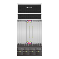
Figure 1-59 Connections between PEMs and PMs
Table 1-74 Mappings between PEMs and PMs
 Loading...