4.2.2.4 Installing Cables
Context
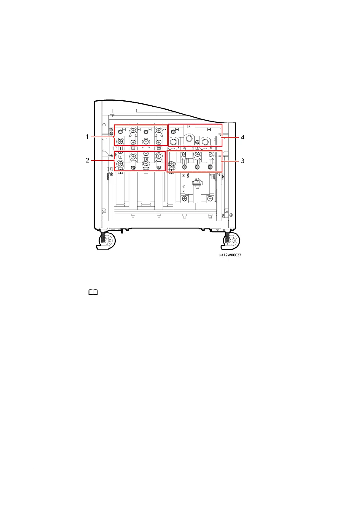
Figure 4-55 Power cable connection positions
(1) Bypass input (N, 2L1–2L3) (2) Mains input (N, 1L1–1L3)
(3) UPS output (N, U, V, W) (4) Battery input (+, N, –)
The 60 kVA UPS is used as an example in the gures and installation procedure. The
installation procedure for the 80 kVA and 120 kVA UPSs is the same as that for the 60 kVA
UPS except for the size of some screws.
The number and colors of cables in the following gures are for reference only.
Procedure
Step 1 Remove the PDU cover from the rear of the chassis.
UPS5000-A-(30 kVA-120 kVA)
User Manual 4 Installation and Cable Connection
Issue 17 (2024-02-21) Copyright © Huawei Digital Power Technologies Co., Ltd. 104
 Loading...