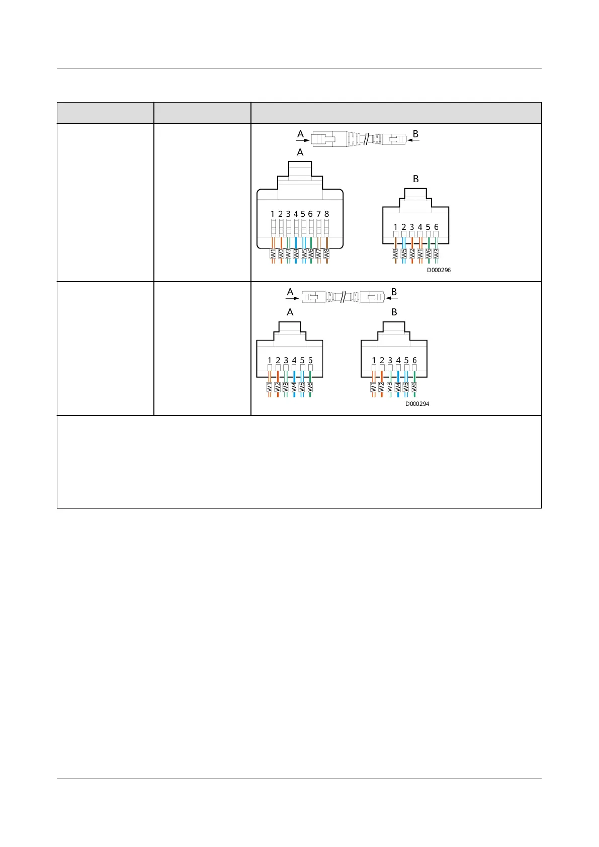
Table 4-7 Cable connection
One End The Other End Cable Connection
RJ11 port (6-pin) RJ45 port (8-pin)
RJ11 port (6-pin) RJ11 port (6-pin)
– One end of the cable is connected to the COM1 port or the RS485-OUT port on the upper-level
T/H sensor. The other end of the cable is connected to the RS485-IN port on the T/H sensor.
– W1: orange-white; W2: orange; W3: green-white; W4: blue; W5: blue-white; W6: green; W7:
brown-white; W8: brown. The cable colors are for reference only. The actual cable colors may
vary.
– Before crimping a terminal, cut o the excess part of core wires.
----End
4.3 Installing a Parallel System
Procedure
Step 1 Ground each UPS in a parallel system separately, and connect power cables and
battery cables.
Step 2 Select a parallel mode and connect cables to the parallel system based on site
requirements.
UPS5000-A-(30 kVA-120 kVA)
User Manual 4 Installation and Cable Connection
Issue 17 (2024-02-21) Copyright © Huawei Digital Power Technologies Co., Ltd. 112
 Loading...