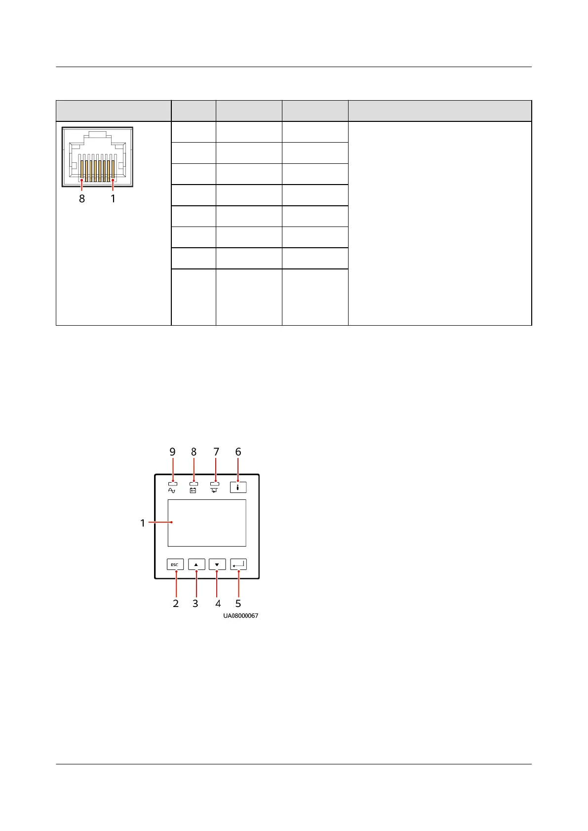
Table 2-3 Pin denitions for the FE and RS485 ports
Appearance Pin FE Port RS485 Port Remarks
1 RJ_TX+ RS485_T+ If cables need to be prepared for the
RS485 port onsite, use any of the
following methods:
● Connect pin 1 and pin 2. Pin 1
connects to RS485+ and pin 2
connects to RS485–.
● Connect pin 4 and pin 5. Pin 4
connects to RS485+ and pin 5
connects to RS485–.
● Connect pins 1, 2, 4, and 5. Twist
cables to pin 1 and pin 4 into
one cable and then connect it to
RS485+. Twist cables to pin 2 and
pin 5 into one and then connect
it to RS485–.
2 RJ_TX– RS485_T–
3 RJ_RX+ -
4 - RS485_R+
5 - RS485_R–
6 RJ_RX- GND
7 - -
8 - -
2.5.4 MDU
The MDU is on the front panel of the UPS. The MDU allows you to control the
UPS, set parameters, and view the running status and alarm information.
Figure 2-24 Appearance
(1) LCD
(2) Back/Shutdown button (3) Up button
(4) Down button (5) Enter/Startup/Mute button (6) Fault indicator/INFO button
(7) Bypass indicator (8) Battery indicator (9) Mains indicator
UPS5000-A-(30 kVA-120 kVA)
User Manual 2 Product Overview
Issue 17 (2024-02-21) Copyright © Huawei Digital Power Technologies Co., Ltd. 47
 Loading...