4.2.1.3 Installing Cables
Context
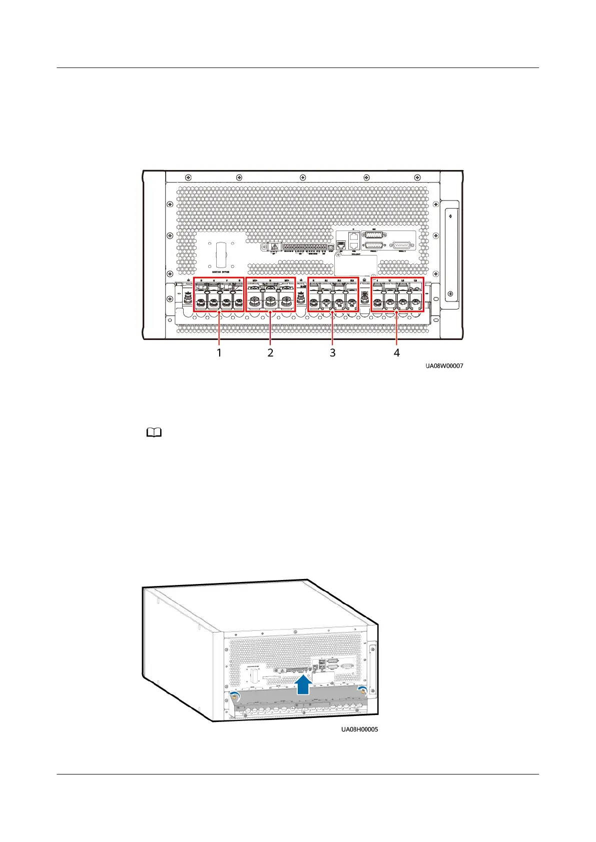
Figure 4-28 Power cable connection positions
(1) UPS output (N, U, V, W) (2) Battery input (BAT+, N, BAT–)
(3) Bypass input (N, 2L1–2L3) (4) Mains input (N, 1L1–1L3)
The rack-mounted installation mode is used as an example to describe how to install
cables.
The number and colors of cables in the following gures are for reference only.
Procedure
Step 1 Remove the terminal block cover.
Figure 4-29 Removing the cover
Step 2 Install ground cables.
UPS5000-A-(30 kVA-120 kVA)
User Manual 4 Installation and Cable Connection
Issue 17 (2024-02-21) Copyright © Huawei Digital Power Technologies Co., Ltd. 87
 Loading...