Serial Communication Programmer Reference Guide
8 810400 Reference Guide Powermax65/85/105 SYNC
Powermax65/85/105 SYNC hardware documents
Refer to the following documents for more information about the required hardware for serial
communications.
You can find these documents on the USB memory stick that came with your plasma power supply,
or with the hardware kits. Technical documentation is also available at www.hypertherm.com/docs
.
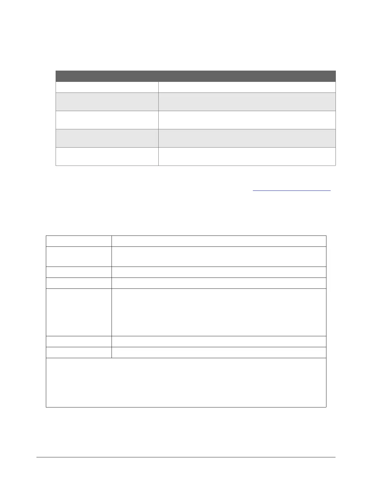
Modbus specifications
Transmission mode and format
How-to Information Document
Order hardware, kits, and cables Powermax65/85/105 SYNC Parts Guide (810490)
Attach a machine torch to a cutting
table
Powermax65/85/105 SYNC Mechanized Cutting Guide (810480)
Install an RS-485 serial interface
connector and board
RS-485 Serial Interface Connector with PCB Field Service
Bulletin (806710)
Install a machine interface receptacle
and voltage divider board
Machine Interface Receptacle with Voltage Divider PCB Field
Service Bulletin (806980)
Connect external serial interface and
machine interface cables
Powermax65/85/105 SYNC Mechanized Cutting Guide (810480)
Mode ASCII (American Standard Code for Information Interchange)
Addressing Controller: CNC
Connected device: Powermax65/85/105 SYNC
Coding system Hexadecimal, ASCII characters 0 - 9, A - F
Baud rate 19200
Bits per byte Start bit: 1
Data bits: 8
• Includes 1 bit for even parity
• Most significant byte (MSB) sent first
Stop bit: 1*
Parity Even**
Error-check field Longitudinal Redundancy Check (LRC)
* The stop bit setting on the plasma power supply and the external control must be the same. By default the
Powermax65/85/105 SYNC plasma power supply is set to 1 stop bit. Refer to CNC settings on the
Powermax65/85/105 SYNC on page 12.
** The parity setting on the plasma power supply and the external control must be the same. By default the
Powermax65/85/105 SYNC plasma power supply is set to Even parity. Refer to CNC settings on the
Powermax65/85/105 SYNC on page 12.