Evaluation Board Manual
Preliminary PPC750FX Evaluation Board
750FXebm_ch5.fm
June 10, 2003
Reset and Interrupts
Page 37 of 115
5. Reset and Interrupts
The following sections provide details regarding the reset and interrupt operation of the board.
5.1 Resets
Reset to the PPC750FX is generated at power-on, by the reset pushbutton, by system-reset from the
PPC750FX (usually in response to a command from the RISCWatch debugger), or by undervoltage on the
+3.3V supply.
Under software control, using registers in the CPLD, each processor can be reset individually, or the entire
board can be reset.
5.2 Interrupts
The system controller contains an interrupt controller that handles interrupts from peripherals inside the
system controller as well as external peripherals.
There are three external interrupt inputs to the PPC750FX (INT, MCP, and SMI). See Table 5-1 for more
detail.
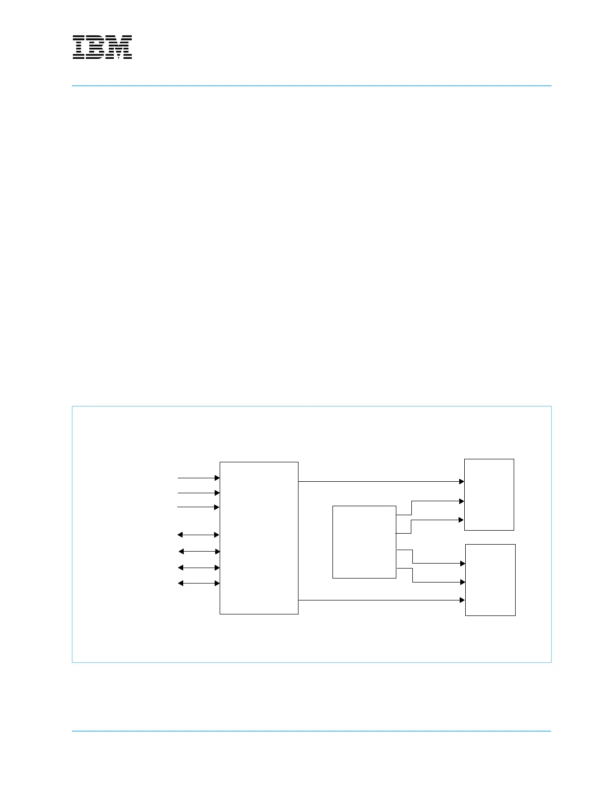
Figure 5-1. Interrupt Architecture
MV64360
System Controller
UART A
UART B
Ethernet PHY
PCI Intr A
PCI Intr B
PCI Intr C
PCI Intr D
CPU 0
CPU 1
CPLD
INT
INT
MCP
SMI
SMI
MCP
Register2