Evaluation Board Manual
Preliminary PPC750FX Evaluation Board
750FXebm_ch6.fm
June 10, 2003
Switches
Page 41 of 115
6.4 CPU 1 PLL Configuration
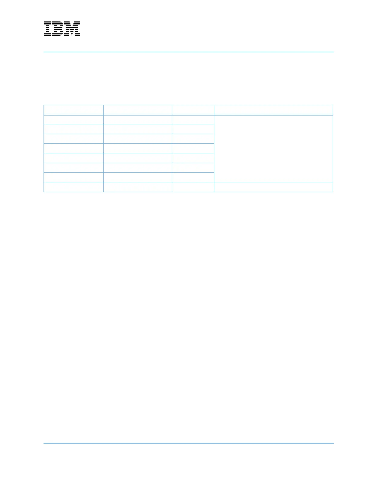
An 8-position DIP switch at location U35 configures PLL for the second PPC750FX processor (U2).
Table 6-5. CPU 1 PLL Configuration Switches—U35
Switch No. Signal Default Setting Description (0 = ON = closed, 1= OFF = open)
1 PLL_CONFIG0 ON
Refer to the latest version of the PowerPC 750FX
RISC Microprocessor Data Sheet for details on the bit
settings for PLL_CONFIG and PLL_RANGE.
2 PLL_CONFIG1 OFF
3 PLL_CONFIG2 ON
4 PLL_CONFIG3 OFF
5 PLL_CONFIG4 OFF
6 PLL_RANGE0 ON
7 PLL_RANGE1 ON
8 SPARESWITCH2 ON Connected to +3.3V pull-up. See CPLD Register1.