Evaluation Board Manual
PPC750FX Evaluation Board Preliminary
Fuses, Batteries, Regulators, and Fans
Page 46 of 115
750FXebm_ch7.fm
June 10, 2003
7.1.2 2.5V Supply
The PPC750FX uses 2.5V for the 60x bus. There is one 2.5V supply on the board. It is identified as VCCA3.
A pair of zero-ohm resistors can be removed to create a connection point or points for current measurement
or external supply connection. Figure 7-1 shows the location of the zero-ohm resistors. Current
measurements can be made between terminals 1 and 2 of either resistor. External supplies should be
connected to terminal 2.
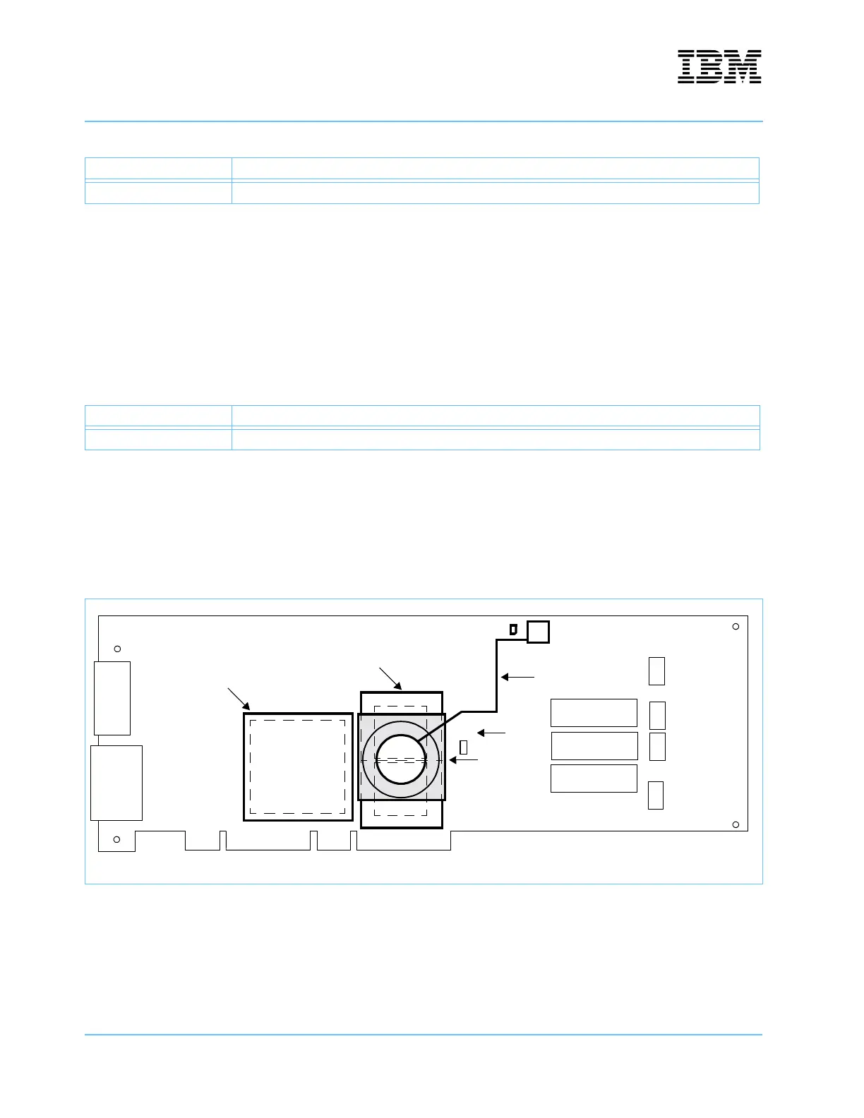
7.2 Fan
There is one fan provided on the board. This fan is mounted on the processor heatsinks and cools both of the
processor chips. See Figure 7-2. The system controller chip has a heatsink attached, but no fan.
The processor fan is connected to J4. If the Ignore Fan jumper at J16 is not installed, programming in the
CPLD activates LED DS3 when a failure is detected at connector J4, and shuts down the power to the
processors and the sytem controller. Disconnecting the fan is detected as a failure.
VCCA2 R307 and R312
Table 7-2. Current Measurement of the 2.5V Supply
Voltage Remove resistors at:
VCCA3 R224 and R226
Figure 7-2. Fan and Heatsink Location Diagram
Table 7-1. Current Measurement of the1.4V Supplies
Voltage Remove resistors at:
System Controller Heatsink
Processor Heatsinks
Fan
J4
Power Cable
DS3
J16
Ignore
Fan