Evaluation Board Manual
PPC750FX Evaluation Board Preliminary
Connectors
Page 66 of 115
750FXebm_ch10.fm
June 10, 2003
10.10 Memory Control
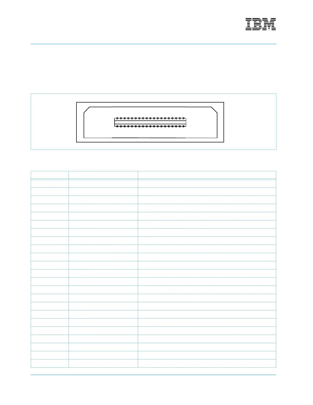
Connection to HP logic analyzers via HP E5346A High Density Probe Adapters is provided by board mounted
connectors, Mictor Part Number 2-767004-2. This connector carries the burst address bus and the chip select
signals from the system controller.
Figure 10-11. Memory Control Connector—J15
Table 10-11. Memory Control Signals—J15
Pin Analyzer Signal Name
1 unused
2 unused
3 GND
4 unused
5 cntl_pod0 – CLK unused
6 cntl_pod1 – CLK unused
7 cntl_pod0 – D15 BADR(2)
8 cntl_pod1 – D15 TESTPIN_A
9 cntl_pod0 – D14 BADR(1)
10 cntl_pod1 – D14 SRAM_LO_CS_N
11 cntl_pod0 – D13 BADR(0)
12 cntl_pod1 – D13 unused
13 cntl_pod0 – D12 SMALL_FLASH_LO_CS
14 cntl_pod1 – D12 unused
15 cntl_pod0 – D11 DEV_WE(3)
16 cntl_pod1 – D11 unused
17 cntl_pod0 – D10 DEV_WE(2)
18 cntl_pod1 – D10 SYSRESET_N
19 cntl_pod0 – D9 DEV_WE(1)
20 cntl_pod1 – D9 CPU1_HRESET_2.5_N
21 cntl_pod0 – D8 DEV_WE(0)
22 cntl_pod1 – D8 CPU1_SRESET_2.5_N
23 cntl_pod0 – D7 CS_TIMING_N
1
2
37
38