Evaluation Board Manual
Preliminary PPC750FX Evaluation Board
750FXebm_ch10.fm
June 10, 2003
Connectors
Page 55 of 115
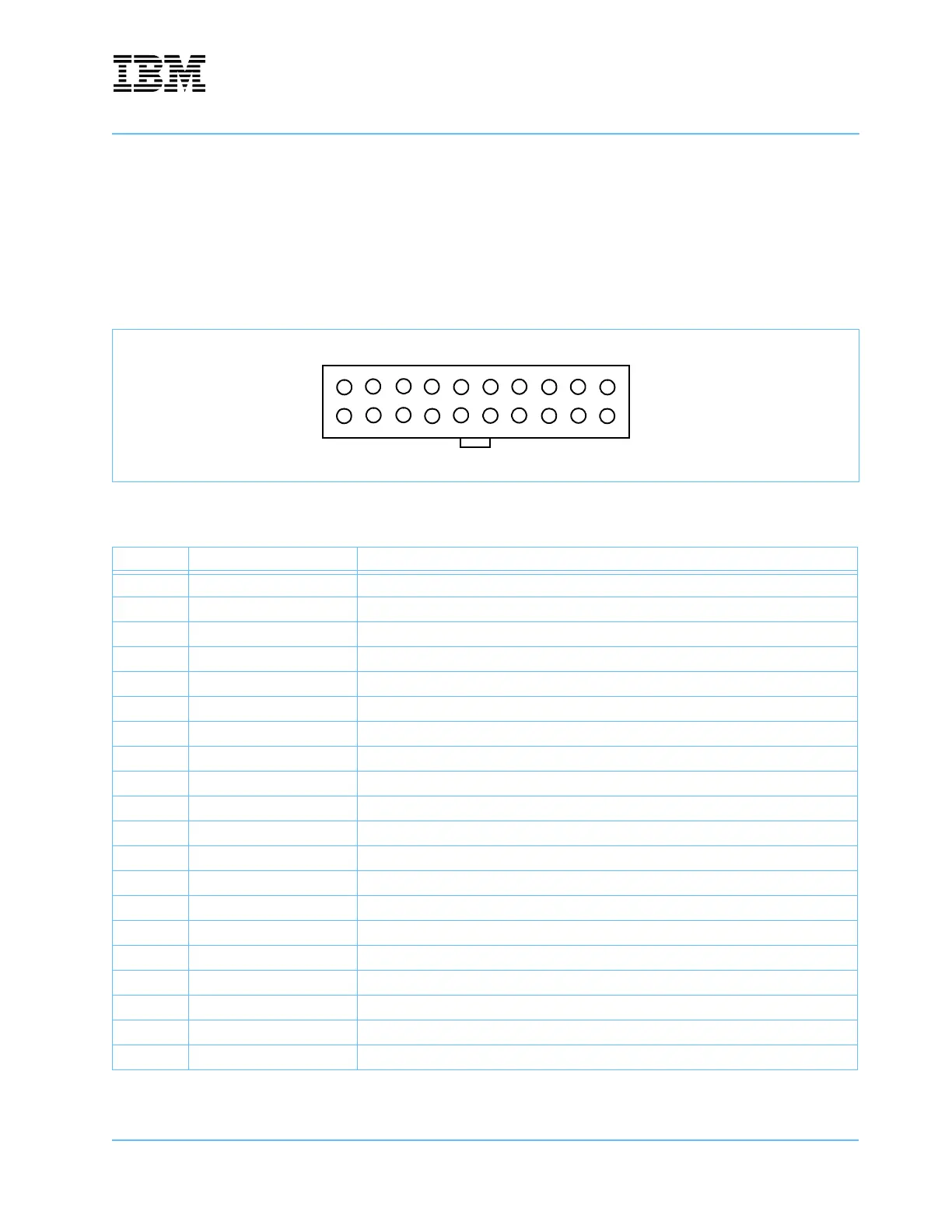
10.1 Auxiliary Power
The board is equipped with a standard ATX power connector. This allows the board to be externally powered
from a standard ATX power supply when it is not installed in a PCI slot.
Note: If the board is plugged into a PCI slot, the external ATX power supply will not activate under any
conditions, and pressing the ATX power-on pushbutton (U53) will have no effect.
Figure 10-2. ATX Power Supply Connector—J34
Table 10-2. ATX Power Signals—J34
Pin Name Comment
1 +3.3V Tolerance ± 4%
2 +3.3V Tolerance ± 4%
3GND
4 +5V Tolerance ± 5%
5GND
6 +5V Tolerance ± 5%
7GND
8 Power OK Active high indicator that +5V and +3.3V are above their undervoltage thresholds
9 +5V SB Standby power, at least 10 mA, tolerance ± 5%
10 +12V Not used
11 +3.3V Tolerance ± 4%. Remote 3.3V sense.
12 -12V Not used
13 GND
14 PS-ON Active low signal that turns on the ATX power supply.
15 GND
16 GND
17 GND
18 -5V Not used
19 +5V Tolerance ± 5%
20 +5V Tolerance ± 5%
12345678910
11 12 13 14 15 16 17 18 19 20