Evaluation Board Manual
PPC750FX Evaluation Board Preliminary
Connectors
Page 68 of 115
750FXebm_ch10.fm
June 10, 2003
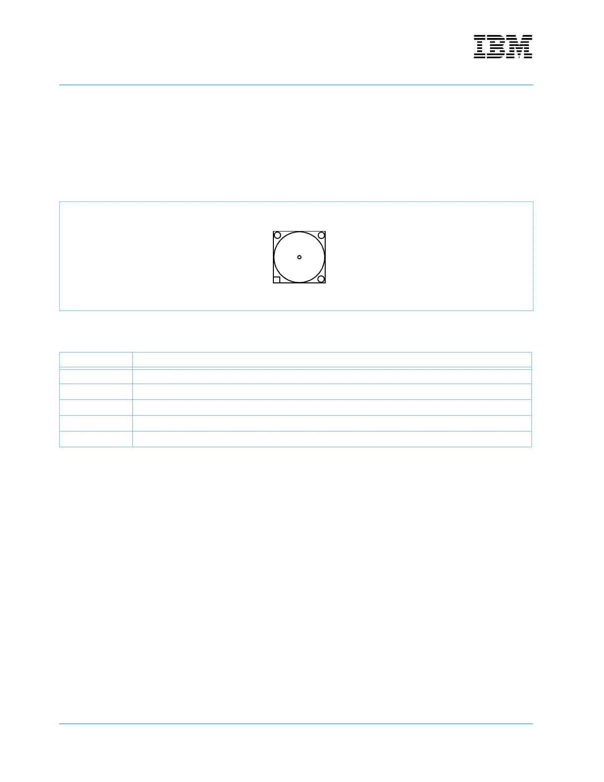
10.11 External Clock Input
An external 133MHz board clock may be provided by an external oscillator connected to this board-mounted
SMA connector. The oscillator output should have 3.3V logic levels. The input impedance to this connector is
approximately 50
Ω.
Note: Board rework is required to use this connector. See the schematic diagrams.
Figure 10-12. External Clock Input Connector—U39
Table 10-12. External Clock Input Signal—U39
Pin Signal Name
1 Ground
2 Ground
3 Ground
4 Ground
5 CLK_EXT
12
34
5