Evaluation Board Manual
Preliminary PPC750FX Evaluation Board
750FXebm_ch6.fm
June 10, 2003
Switches
Page 39 of 115
6. Switches
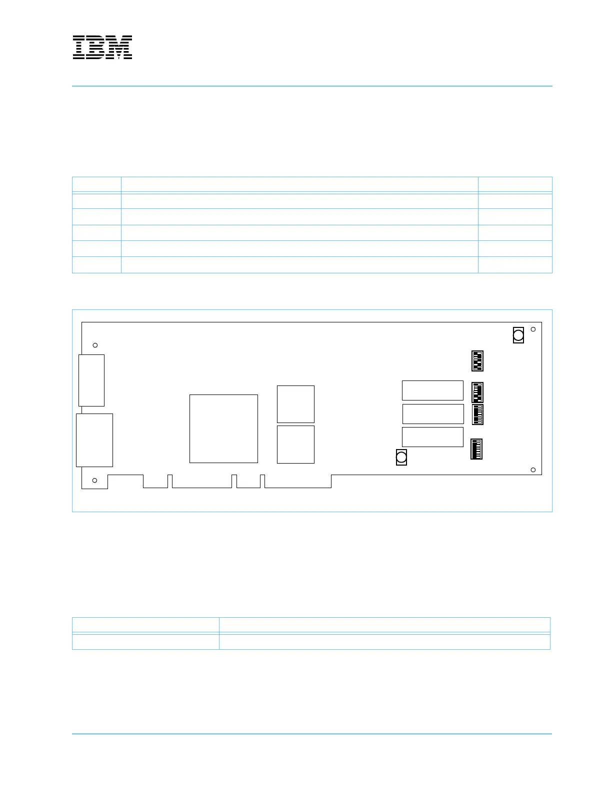
This section shows the location of all the switches on the board, and explains the function of each switch.
6.1 Reset Pushbutton
When pressed, the pushbutton switch at U5 pulls the PWRGD signal to ground, causing a reset of the board.
Table 6-1. Switches
Location Function Page
U5 Reset pushbutton 39
U17, U24 System controller initialization 42
U30 CPU 0 PLL configuration 40
U35 CPU 1 PLL configuration 41
U53 External ATX power 40
Figure 6-1. Switch Location Diagram
Table 6-2. Reset Pushbutton—U5
Signal Description (0 = ON = close)
Pulls down PWRGD. Main board reset.
U5
Reset
U17
On
Off
1
8
U24
U30
U35
1
8
1
8
1
8
On
Off
On
Off
U53
ATX Power