Evaluation Board Manual
Preliminary PPC750FX Evaluation Board
750FXebm_ch10.fm
June 10, 2003
Connectors
Page 59 of 115
10.6 PCI Connector
This evaluation board is a PCI card. It has a standard PCI connector that plugs into a standard +3.3V or +5V
PCI socket on a PC system board. The signals on the PCI conector are the standard set of PCI signals.
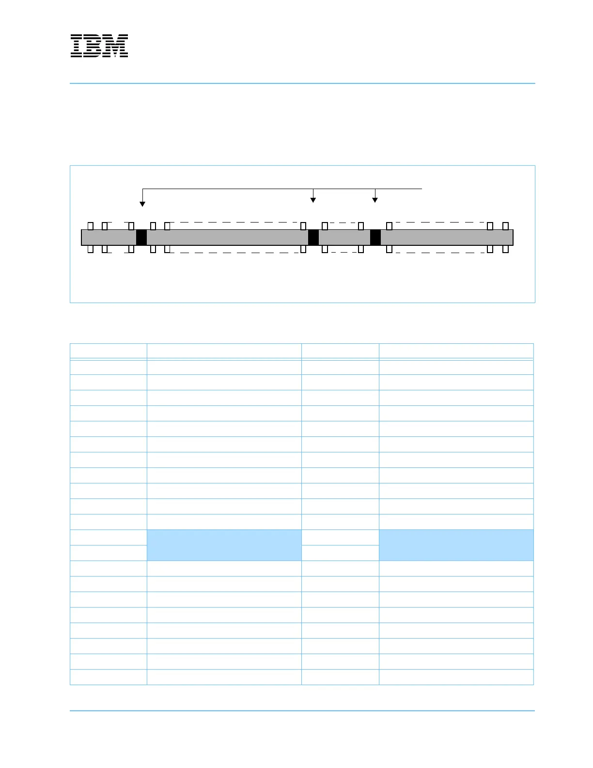
Figure 10-7. PCI Connector—J25
Table 10-7. PCI Connector Signals—J25
Pin Signal Pin Signal
B1 -12V A1 TRST
B2 TCK A2 +12V
B3 GND A3 TMS
B4 TDO A4 TDI
B5 +5V A5 +5V
B6 +5V A6 INTA
B7 INTB A7 INTC
B8 INTD A8 +5V
B9 PRSNT1 A9 Reserved
B10 Reserved A10 +3.3V (I/O)
B11 PRSNT2 A11 Reserved
–
Key slot
–
Key slot
––
B14 Reserved A14 +3.3V (Aux)
B15 GND A15 RST
B16 CLK A16 +3.3V (I/O)
B17 GND A17 GNT
B18 REQ A18 GND
B19 +3.3V (I/O) A19 Reserved
B20 AD31 A20 AD30
B21 AD29 A21 +3.3V
B1 B62B11 B14
A1 A62A11 A14
B63 B94
A63 A94
Note: This view of the connector is from the top edge of the card.
Key slots
B52
A52
A49
B49