EasyManuals Logo

IBM PPC750FX User Manual

IBM PPC750FX
116 pages
To Next Page IconTo Next Page
To Previous Page IconTo Previous Page
Page #57 background imageLoading...
Page #57 background image
Evaluation Board Manual
Preliminary PPC750FX Evaluation Board
750FXebm_ch10.fm
June 10, 2003
Connectors
Page 57 of 115
10.4 RISCWatch JTAG Debugger
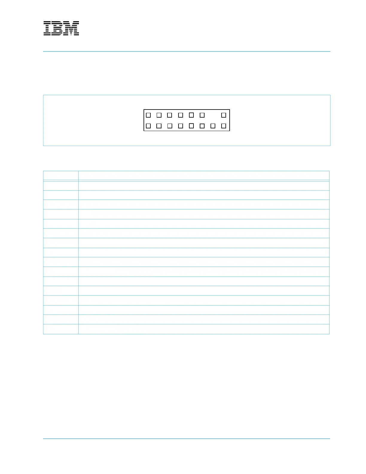
The RISCWatch JTAG debugger connects to the board through a 2x8 header.
Figure 10-5. RISCWatch JTAG Connector—J11
Table 10-5. RISCWatch Signals—J11
Pin Signal Name
1TDO
2 unused
3TDI
4TRST_N
5 unused
6PWRSENSE
7TCK
8 unused
9TMS
10 unused
11 SRESET_N
12 unused
13 HRESET_N
14 Key—no pin at this location.
15 CHECKSTOP_N
16 GND
115
216

Table of Contents

Questions and Answers:

Question and Answer IconNeed help?

Do you have a question about the IBM PPC750FX and is the answer not in the manual?

IBM PPC750FX Specifications

General IconGeneral
BrandIBM
ModelPPC750FX
CategoryMotherboard
LanguageEnglish

Related product manuals