Evaluation Board Manual
Preliminary PPC750FX Evaluation Board
750FXebm_ch10.fm
June 10, 2003
Connectors
Page 63 of 115
10.8 Serial Ports
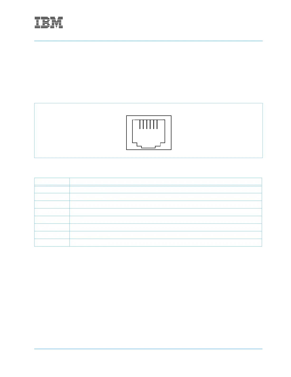
Serial Port 1 (J13 Right) and Serial Port 2 (J13 Left) are provided through standard RJ11/12 connectors, as
shown in Figure 10-9. Both serial port interfaces are provided by the ST16C2552 attached to the system
controller and support only four RS-232 signals.
Table 10-9 describes the pin assignments for Serial Ports 1 and 2. Note that DTR appears on both pins 2
and 7.
Figure 10-9. Serial Port Connector—J13, one of two RJ11/12 sockets
Table 10-9. Serial Port Connector Signals—J13, both ports
Pin Signal Name
1 Empty contact position
2DTR
3DSR
4Rx
5 Frame Ground
6Tx
7DTR
8 Empty contact positiont
1234567
8