v The server supports a maximum of 12 DIMMs (single-rank, dual-rank, or
quad-rank) on the system board. If you mix single-rank, dual-rank, or quad-rank
DIMMs in the server, quad-rank DIMMs must be installed first. When one
quad-rank DIMM is installed, it must be installed in DIMM slot 1.
v The DIMM options that are available for the server are 2 GB, 4 GB, 8 GB, 16 GB,
and 32 GB (when available).
Note: While installing 16 GB 1.5 Volt/ 32 GB 1.35 Volt, please refers to the table
of fan configuration instruction.
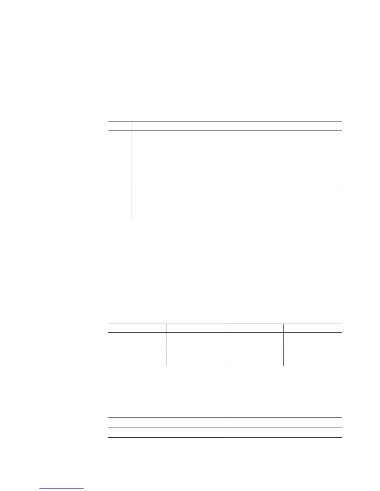
Table 25. Fan configuration instruction
Fans Conditions
2 and
Rear
fan
Standard for all systems
3
1. When the second microprocessor is populated, the fan is included in the
second microprocessor kit, P/N: 00D2581 ~ 00D2589. Or
2. When more than 2 PCI-e adapters have been installed on the system, the fan
(P/N: 00D2593) will be available separately.
1 Optional redundant fan (P/N: 00D2593)
Attention: When fan 3 is installed and 16 GB 1.5V / 32 GB 1.35V DIMMs are
installed, fan 1 must also be populated.
v The server system board supports a minimum of 2 GB and a maximum of 96 GB
of system memory.
Note: The amount of usable memory is reduced depending on the system
configuration. A certain amount of memory must be reserved for system
resources. To view the total amount of installed memory and the amount of
configured memory, run the Setup utility. For additional information, see
“Configuring the server” on page 112.
v The server system board provides three memory channels for each
microprocessor and each memory channel supports up to two DIMMs. The
following table lists the DIMM connectors on each memory channel:
Table 26. DIMM connectors on each memory channel
Microprocessor Channel 0 Channel 1 Channel 2
Microprocessor 1 DIMM connectors 1
and 2
DIMM connectors 3
and 4
DIMM connectors 5
and 6
Microprocessor 2 DIMM connectors 7
and 8
DIMM connectors 9
and 10
DIMM connectors 11
and 12
v The following table shows the DIMM connectors that are associated with each
microprocessor:
Table 27. DIMM connectors associated with each microprocessor
Microprocessor
DIMM connectors associated with the
microprocessor
Microprocessor 1 1 through 6
Microprocessor 2 7 through 12
Chapter 6. Removing and replacing components 405

 Loading...


