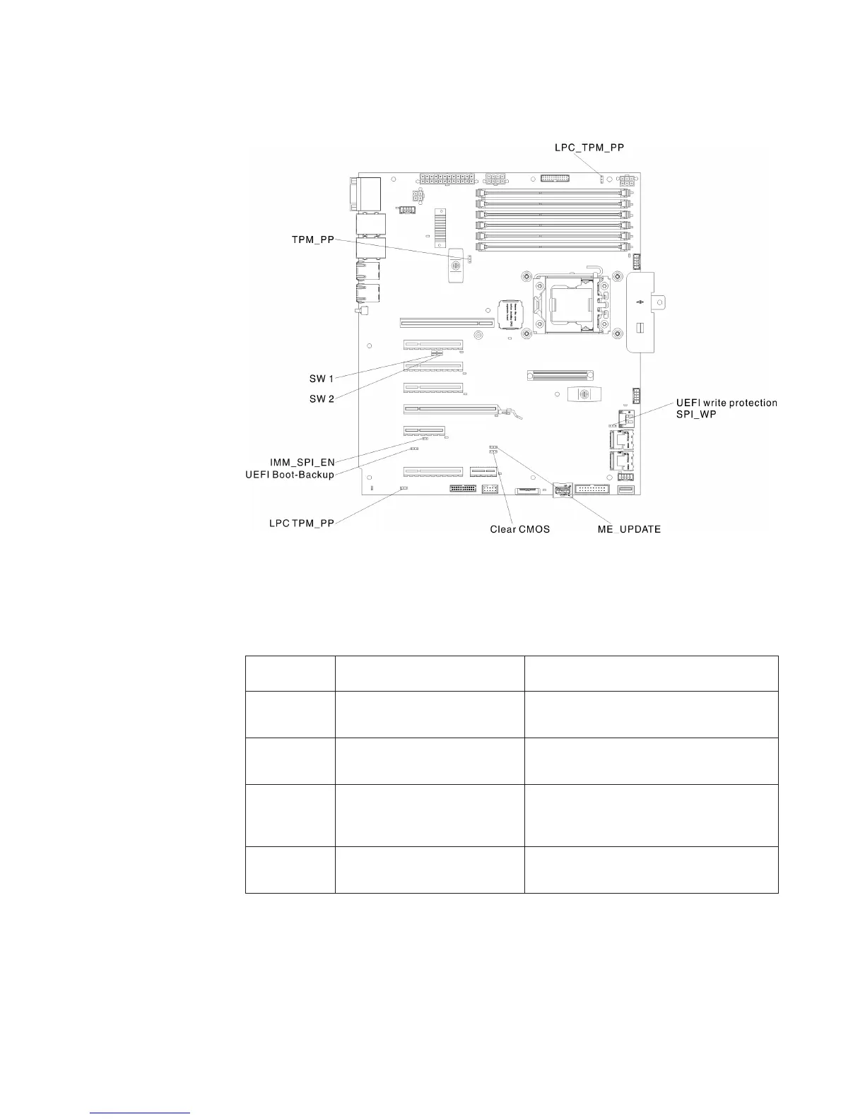
System-board switches and jumpers
The following illustration shows the jumper locations.
Note: If there is a clear protective sticker on the top of the switch blocks, you must
remove and discard it to access the switches.
The following table describes the jumper on the system board.
Table 4. System board jumpers
Jumper
number Jumper name Jumper setting
ME_UPDATE PCH ME firmware update
v Pins 1 and 2: Normal mode (default)
v Pins 2 and 3: Force update mode
Clear CMOS CMOS clear jumper
v Pins 1 and 2: Normal mode (default)
v Pins 2 and 3: Clear CMOS
SPI-WP UEFI flash write protection
v Pins 1 and 2: GPIO controls write
protection (default)
v Pins 2 and 3: Force write protection
UEFI
Boot_Backup
UEFI boot - block selection
v Pins 1 and 2: Boot normal (default)
v Pins 2 and 3: Boot backup
Chapter 2. Installing optional devices 31
 Loading...


