10
2
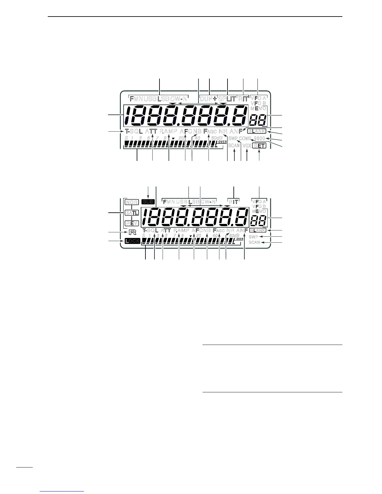
PANEL DESCRIPTION
q FREQUENCY READOUTS (p. 22)
Shows the operating frequency.
•Settingitemnameisindicatedduringsetmode.(p.55)
w MODE INDICATOR (p. 23)
Shows the selected operation mode.
e TUNING STEP INDICATOR (p. 22)
Appears when the 1 kHz or 1 MHz tuning step is
selected.
r DUPLEX INDICATOR (p. 34)
Either“DUP–”or“DUP+”appearsduringduplex(re-
peater) operation.
t SPLIT INDICATOR (p. 37)
Appears during split operation.
y RIT INDICATOR (p. 27)
➥ Appears while the RIT function is activated.
➥ Flashes while the SUB dial function is activated.
u VFO INDICATOR (p. 21)
Either VFO A or VFO B appears during VFO opera-
tion.
i MEMORY MODE INDICATORS/MEMORY
CHANNEL NUMBER READOUTS (p. 40)
The memory mode indicator appears during mem-
ory mode operation and the memory channel num-
ber readout shows the selected memory channel
number during both the memory and VFO mode
operation.
Memory channel number readout
In addition to the memory channel number indication, the
memory channel number readout indicates 10 Hz and 1 Hz
digits of operating frequency while rotating the tuning dial in
SSB or CW mode with 10 or 1 Hz tuning step. After 2 sec.
from tuning dial operation, the readout indicates the memo-
ry channel number.
o AUTO NOTCH FILTER INDICATOR (p. 31)
Appears when the optional DSP unit, UT-106, is in-
stalled, and the ANF (Automatic Notch Filter) func-
tion is activated.
!0 BLANK INDICATOR (p. 42)
Appears when the selected memory channel has
not been programmed or has been cleared.