47
9
CONNECTIONS AND MAINTENANCE
9
y DC POWER CONNECTOR
Connects the supplied DC power cable from this connec
-
tor to an external 13.8 V DC power source.
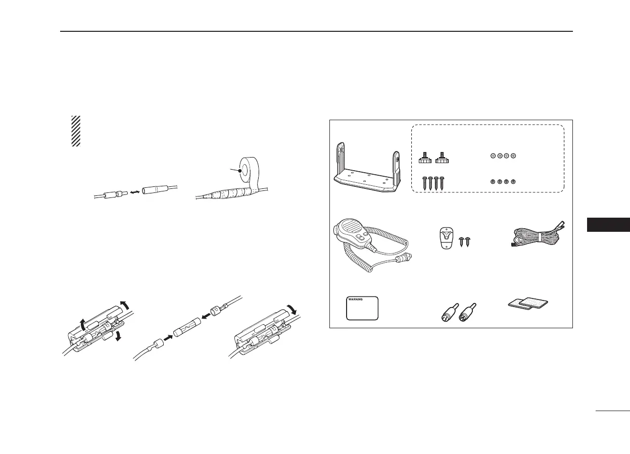
CAUTION: After connecting the DC power cable, cover
the connectors with a rubber vulcanizing tape shown
below, to prevent water seeping into the transceiver.
■ Fuse replacement
One fuse is installed in the supplied DC power cable. If a
fuse blows or the transceiver stops functioning, track down
the source of the problem, if possible, and replace the dam
-
aged fuse with a new, rated one.
■ Supplied accessories
The following accessories are supplied
Mounting bracket For mounting bracket
Knob bolts
Screws (5×20 mm)
Flat washers (M5)
Spring washers (M5)
Microphone hanger
and screws (3×16 mm)
Microphone DC power cable
Warning sticker SpongesAccessory connectors
(3 pin, 6 pin)
■ Antenna
A key element in the performance of any communication
system is an antenna. Ask your dealer about antennas and
the best place to mount them.

 Loading...


