50
9
CONNECTIONS AND MAINTENANCE
■ UT-112/UT-98* installation
CAUTION: DISCONNECT the DC power cable from the
transceiver before performing any work on the trans
-
ceiver. Otherwise, there is danger of electric shock and/or
equipment damage.
Follow the case opening procedure shown here when you
want to install an optional unit (UT-112 or UT-98*).
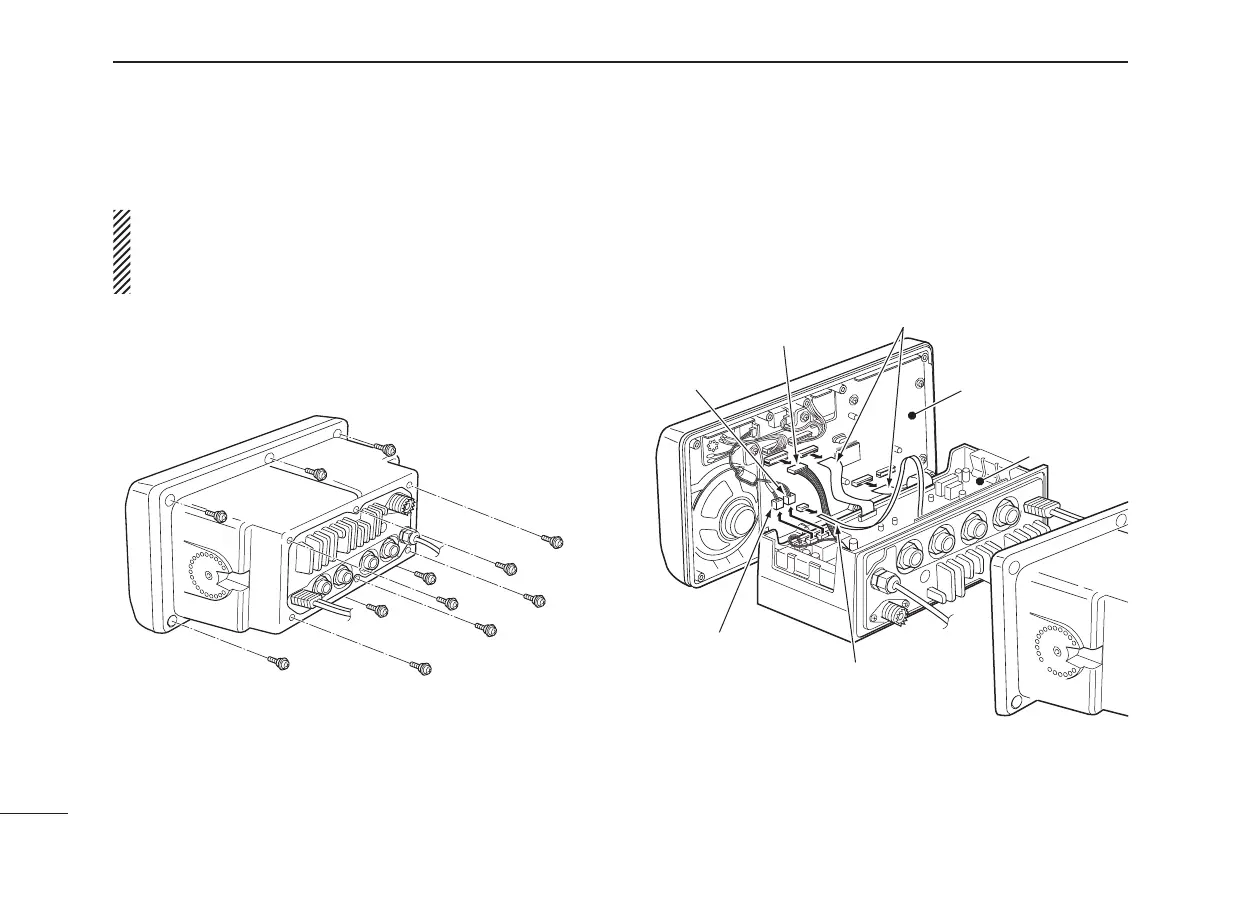
q Remove the 12 screws and open the transceiver.
* The UT-98 is the discontinued model, and the current
model is the UT-112.
w Turn the transceiver upside down, then disconnect the flat
cables and Rear mic control (6-pin) from LOGIC board,
and Front mic control (2-pin) and Volume control (3-pin)
from AF board.
Flat cable
Flat cables
LOGIC
board
Front mic (2-pin)
Volume
(3-pin)
Rear mic
(6-pin)
AF board

 Loading...


