9393
12
CONNECTIONS AND MAINTENANCE
1
2
3
4
5
6
7
8
9
10
11
12
13
14
15
16
z Connects to NMEA 0183 In lines of a GPS receiver for
position data.
• A GPS receiver compatible with NMEA 0183 format RMC,
GGA, GNS, or GLL and VTG sentences is required. Ask
your dealer about suitable GPS receivers.
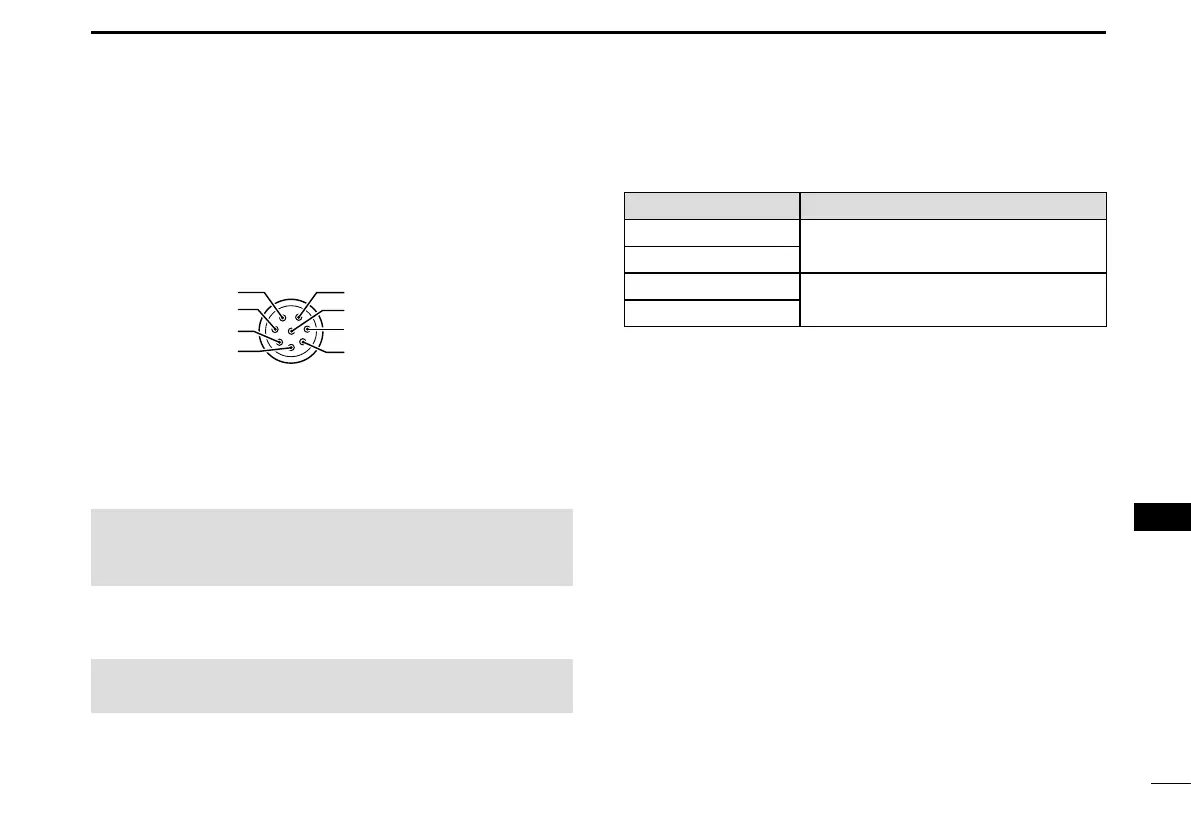
Transceiver’s rear panel view
NMEA 1 IN (+)
NMEA 1 IN (–)
NMEA 1 OUT (+)
NMEA 2 OUT (–)
NMEA 2 IN (–)
NMEA 2 IN (+)
NMEA 1 OUT (–)
NMEA 2 OUT (+)
u NMEA 2000 CONNECTOR
Connects to the NMEA 2000 network.
i GPS ANTENNA CONNECTOR
Connects the supplied GPS antenna.
NOTE: Be sure the GPS antenna is positioned where the
GPS antenna has a clear view to receive signals from
satellites.
o ANTENNA CONNECTOR
Connects to a marine VHF antenna with a PL-259 connector.
CAUTION: Transmitting without an antenna may damage
the transceiver.
D NMEA 0183 In/Out lines specications
PIN SPECIFICATIONS
NMEA 0183 OUT (+)
Output level: 5 V/40 mA maximum
(RS-422 balanced type)
NMEA 0183
OUT (–)
NMEA 0183
IN (+) Input level: Less than 2 mA
(at 2 V applied)
NMEA 0183
IN (–)
D Connecting the MA-500TR
Connect the transceiver to the high density D-Sub 15-pin
connector of the MA-500TR using the OPC-2014* cable.
* The OPC-2014 is supplied with the MA-500TR
• NMEA 1 OUT (+) or NMEA 2 OUT(+):
Connects to lead 3 of the OPC-2014.
• NMEA 1 OUT (–) or NMEA 2 OUT(–):
Connects to lead 2 of the OPC-2014.
• NMEA 1 IN (+) or NMEA 2 IN (+):
Connects to lead 5 of the OPC-2014.
• NMEA 1 IN (–) or NMEA 2 IN (–):
Connects to lead 4 of the OPC-2014.