97
12
CONNECTIONS AND MAINTENANCE
New2001
1
2
3
4
5
6
7
8
9
10
11
12
13
14
15
16
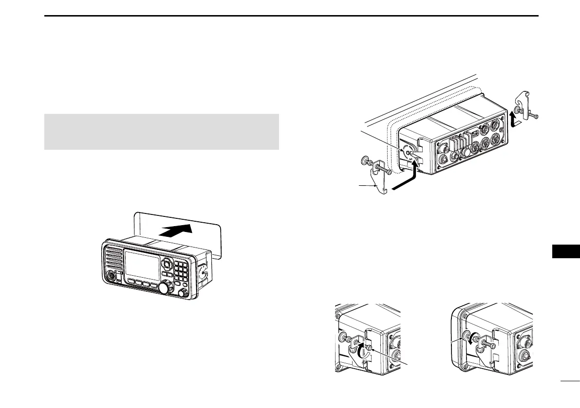
■ MB-75 installation
An optional MB-75 flush mount kit is used to mount the
transceiver to a at surface such as an instrument panel.
CAUTION: Keep the transceiver and microphone at least
1 meter (3.3 feet) away from your vessel’s magnetic
navigation compass.
1. Using the template comes with the transceiver,
carefully cut a hole in the instrument panel, or wherever
you plan to mount the transceiver.
2. Slide the transceiver through the hole, as shown below.
3. Attach the 2 supplied (M5 × 8 mm) bolts on both sides
of the transceiver.
4. Attach the clamps on both sides of the transceiver.
5. Make sure that the clamps align parallel to the
transceiver’s body.
6. Tighten the end bolts on the clamps (rotate clockwise)
so that they press rmly against the inside of the
instrument control panel. (Torque: 0.6 N•m)
7. Tighten the locking nuts (rotate counterclockwise) so
that the transceiver is securely mounted in position, as
shown below.
8. Connect the antenna and power cable, then return the
instrument control panel to its original place.
Supplied
bolt
Clamp
Locking
nut
End bolt