4
2
PANEL DESCRIPTION
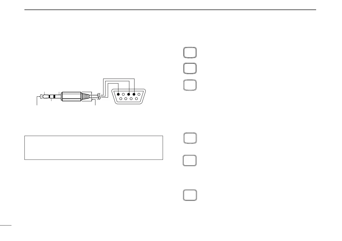
!0 [DATA] JACK
Connect to a PC or GPS receiver via the RS-232 cable (D-
sub 9 pin) for data communication in the RS-232 format.
D Keypad
[A•
FUNC
]
Access to secondary function.
[B•
CALL
]
Selects the call channel. (p. 21)
[C•
MR
]
➥ Selects a memory mode. (p. 21)
➥ After pushing [A•
FUNC
], enter into memory pro-
gramming/editing mode. (pgs. 22–24)
➥ After pushing [A•
FUNC
], programs/transfers
VFO/memory or call channel contents into
memory channel/VFO when pushed and held
for 1 sec. (pgs. 22–24)
[D•
CLR
]
Selects VFO mode, aborts direct frequency input,
or cancels scanning, etc. (pgs. 13, 30)
[1•
TONE
]
➥ Input digit “1” during frequency input, memory
channel selection, etc. (pgs. 13, 21)
➥ After pushing [A•
FUNC
], selects the subaudible
tone function. (pgs. 17, 34)
[2•
P
.
BEEP
]
➥ Input digit “2” during frequency input, memory
channel selection, etc. (pgs. 13, 21)
➥ After pushing [A•
FUNC
], turns the pocket beep
function ON and OFF. (p. 36)
When making the connection between your transceiver and
PC or other device, ensure that the correct connections are
made otherwise data communications may fail.

 Loading...