2 Multi-State Lamp
9-22 WindO/I-NV4 User’s Manual
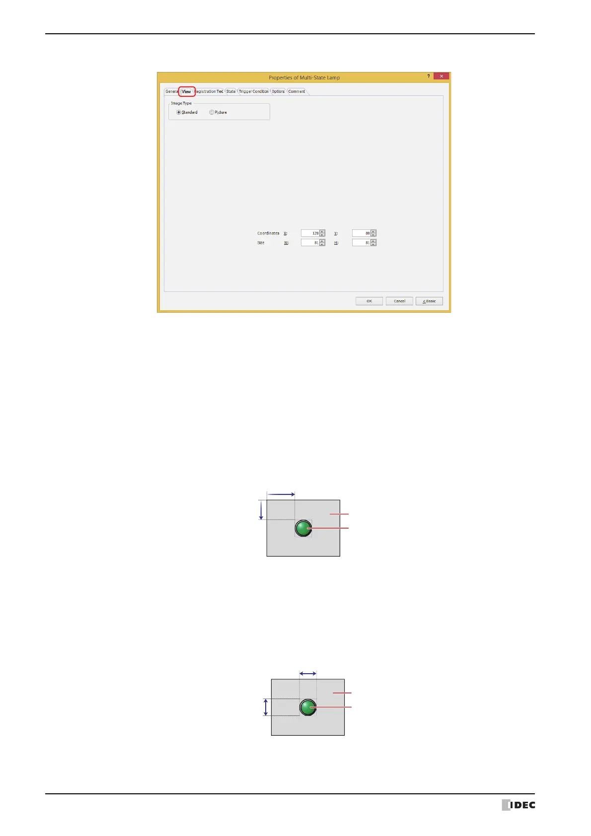
● View Ta b
■ Image Type
Select the type of graphic to be used to represent the part.
■ Coordinates
■ Size
Standard: Uses the default graphic for WindO/I-NV4.
Picture: Uses an image file saved using Picture Manager.
For details about image file restrictions, refer to Chapter 2 “1.4 Available Image Files” on page 2-20.
X, Y: Sets the display position of parts using coordinates.
The X and Y coordinates of parts is defined relative to an origin at the top-left corner of the screen.
X: 0 to (base screen horizontal size - 1)
Y: 0 to (base screen vertical size - 1)
Sets width and height to define the size of parts. The minimum size varies based on the item selected for Image Type.
Standard: The minimum size varies based on the selected item and the maximum size is a base screen size.
Picture: W: 2 to (base screen horizontal size)
H: 2 to (base screen vertical size)
Width
Height
Screen
Parts
 Loading...