FC6A S
ERIES
M
ICRO
S
MART
A
LL
-
IN
-O
NE
T
YPE
U
SER
’
S
M
ANUAL
FC9Y-B1722 2-71
2: P
RODUCT
S
PECIFICATIONS
Terminal Arrangement and Wiring Examples
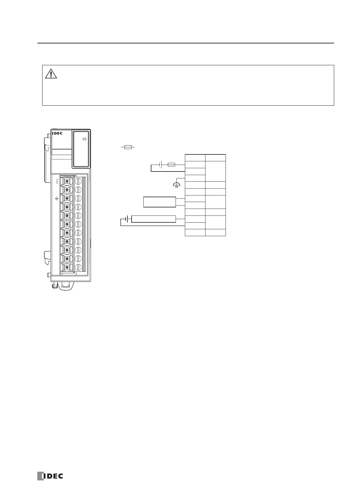
■ FC6A-J2C1
• When connecting the terminal, insert an IEC 60127-approved fuse suitable for the applied voltage and current draw at
the position shown in the following diagram.
(Applicable when equipment containing the FC6A Series MicroSmart is destined for Europe)
• Do not connect a thermocouple to a part with hazardous voltage (60V DC or peak 42.4V DC or higher part).
• Before turning on the power, always check the wiring. If wiring is incorrect, the analog I/O module may be damaged.
Terminal block type Applicable Connector: FC6A-PMTB11PN02 (screw fastened type),
FC6A-PMSB11PN02 (spring clamp type)
For wiring precautions, see "Input/Output Wiring" on page 3-15.
PWR
ANALOG
FC6A-J2C1
NC I1- I1+ NC I0- I0+ NC NC 0V
24V
: Fuse
0V
24V
Terminal No.
I/O
FG
NC
I1+
I1-
NC
NC
I0+
I0-
NC
24V DC
NC
NC
NC
IN0
IN1
NC
-
+
+
-
Analog Voltage/
current Output Device
2-wire Analog Output Sensor
-
+