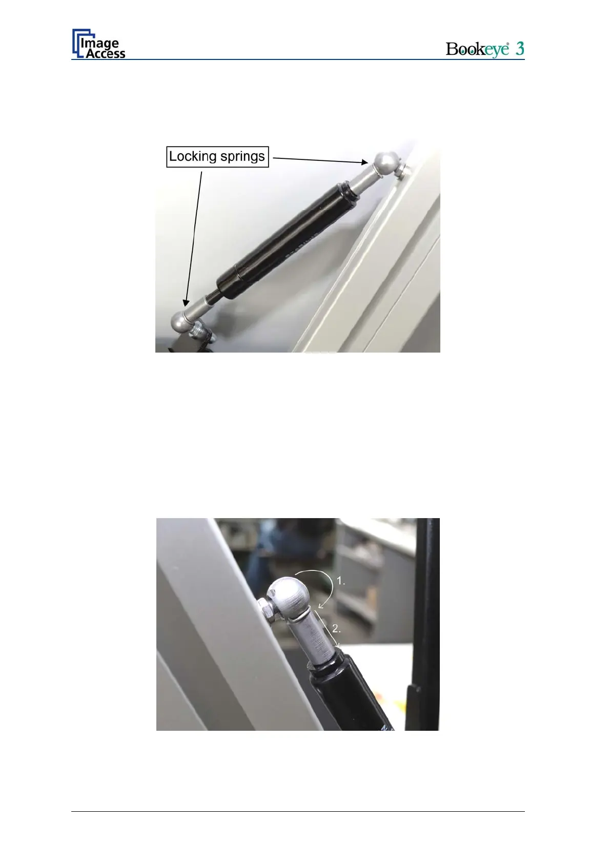
Each gas spring has on its ends special locking springs inserted.
Important: The locking springs always must be removed before placing or removing
the gas springs at the glass plate or on the pin at the lamps.
Picture 34: Position of locking springs
Picture 34 shows the position of the locking springs at the lamp and at the glass plate.
When the scanner is delivered, the gas springs are already mounted to the lamps. They
only must be mounted to the glass plate.
To mount the gas springs to the glass plate, remove only the locking spring at the glass
plate side of the gas spring.
At first turn the locking spring (1.) over the ball head of the gas spring. It needs a little
force to move the spring over the ball head.
Then pull it out of the boreholes (2.).
Picture 35: Removing the locking spring
Page 30 Setup and Assembly Manual
 Loading...