46
INSTALLERUSERMAINTENANCE TECHNICIANTECHNICAL DATA
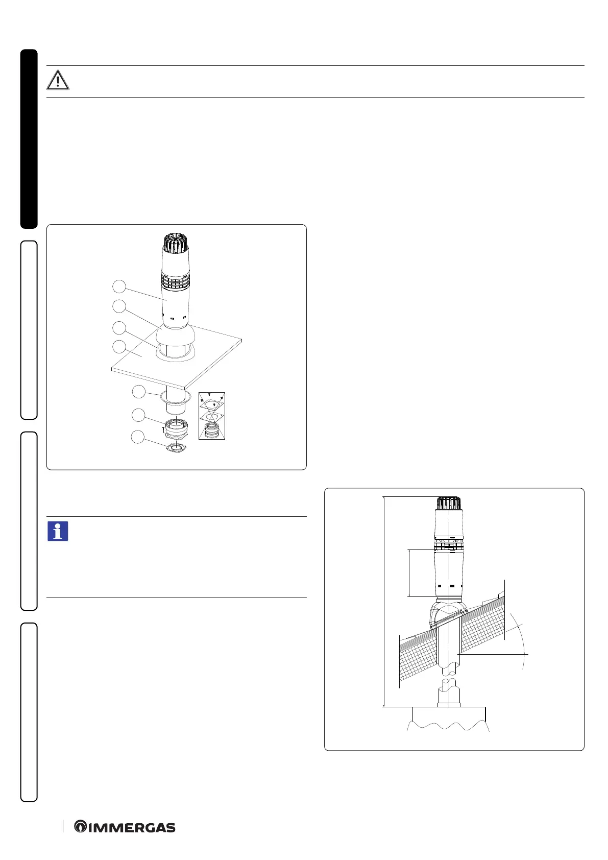
Vertical kit assembly with aluminium slate Ø80/125 (Fig. 26)
To install the kit Ø 80/125 one must use the adapter kit (pos. 2, Fig. 26).
1. Install the anged adaptor (2) on the central hole of the appliance, positioning gasket (1) with the circular projections downwards in
contact with the appliance ange.
Imitation aluminium slate installation:
2. Tighten the concentric ange with the screws in the kit.
3. Replace the slates with the aluminium sheet (4), shaping it to ensure that rainwater runs o.
4. Position the xed half-shell (5) on the aluminium slate;
5. Insert the intake-exhaust terminal (7);
6. Fit the Ø 80/125 concentric terminal pipe with the male side (smooth) to the female side of the adapter (1) (with lip seals) up to the end
stop, making sure that the wall sealing plate (3) has been tted; this will ensure sealing and joining of the elements making up the kit.
C
33
1
2
3
4
5
6
7
26
e adaptor kit includes (Fig. 26):
N° 1 Gas ke t (1)
N°1 Adapter Ø 80/125 (2)
e Ø 80/125 kit includes (Fig.26):
N°1 Wall sealing plate (3)
N°1 Aluminium slate (4)
N°1 Fixed half-shell (5)
N°1 Mobile half-shell (6)
N°1 Concentric intake/exhaust pipe Ø 80/125 (7)
e remaining kit components must not be used
Extensions for vertical kit Ø 80/125 (L = maximum length)
(Fig. 27).
To calculate the length of the ue, simply add, for each
component you intend to use, the corresponding value
indicated in the column "Length equivalent to m of pipe"
in the table in par. 1.14, and check that the resulting sum
is equal to or less than the maximum length indicated in
par. 1.15.
C
33
265 mm
≤
27