TechDoku_CC1000_VCC1000_CC3000_VCC3000_GenPM_GB_86025010_86025110.doc
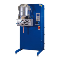
Figure 14: antenna of modem
Modem with antenna: Enables INDUTHERM online
diagnosis. The modem is inside. To achieve stable
connections the antenna might be moved. The modem
is connected, if the red led inside is flashing and Op. A
at service page 2 show you value like Op.A = 10 to 25.
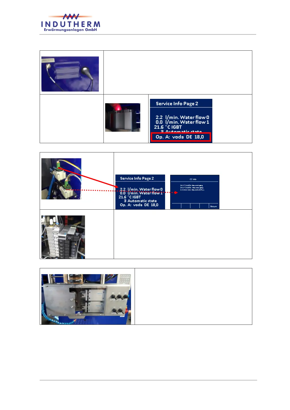
Figure 15: status LED
of modem
Figure 16: status LED of modem
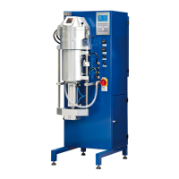
Inside: water sensor: Flow meter for both cooling
lines (generator and die cooler). The faster the LED
flashing, the more is the water flow.
Inside valve battery: Valve 0-7. Function ex-
plained in connection diagram – digital I/O.
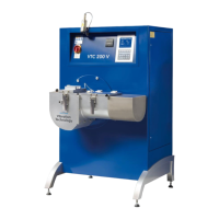
Drawing unit:
Illustrated with 5 wire option and five single
pressure cylinders (only for (V)CC3000).
The protective cover is transparent.