TechDoku_CC1000_VCC1000_CC3000_VCC3000_GenPM_GB_860
25010_86025110.doc
10 Annexe
10.1 List of figures
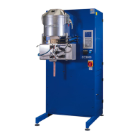
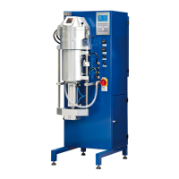
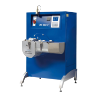
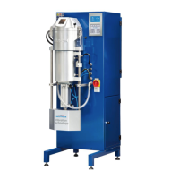
Figure 1: overall view ..................................................................... 4–2
Figure 2: Front connection and additional control elements ........... 4–4
Figure 3: backside of the vacuum pressure casting machine ......... 4–5
Figure 4: Setup of the crucible chamber ........................................ 4–6
Figure 5: die cooler ........................................................................ 4–7
Figure 6: round die cooler .............................................................. 4–7
Figure 7: vacuum die cooler........................................................... 4–7
Figure 8: pressure draw roll regulator ............................................ 4–7
Figure 9: Draw roll switch .............................................................. 4–7
Figure 10: main switch ................................................................... 4–8
Figure 11: oxidation protection ....................................................... 4–8
Figure 12: secondary chiller ........................................................... 4–8
Figure 13: LED-light ....................................................................... 4–8
Figure 14: antenna of modem ........................................................ 4–9
Figure 15: status LED of modem ................................................... 4–9
Figure 16: status LED of modem ................................................... 4–9
Figure 17: water sensors ............................................................... 4–9
Figure 18: valve battery ................................................................. 4–9
Figure 19: drawing unit .................................................................. 4–9
Figure 20: backside of casting unit............................................... 4–10
Figure 21: Quattro-option ............................................................. 4–10
Figure 22: Bending unit option ..................................................... 4–10
Figure 23: granulation tank .......................................................... 4–11
Figure 24: option vacuum sealed hinged window ......................... 4–12
Figure 25: option refill system ...................................................... 4–13
Figure 26: lifting the weight ............................................................ 5–1
Figure 27: constant pressure regulator .......................................... 6–3
Figure 28: data management software menu ................................. 6–4
Figure 29: casting log .................................................................... 6–4
Figure 30: Main Screen .................................................................. 7-8
Figure 31: Info screen ................................................................... 7-10
Figure 32: pre-set casting programs ............................................. 7-11
Figure 33: System parameter ....................................................... 7-12
Figure 34: Service-Info-Page 1 ..................................................... 7-13
Figure 35: Service-Info-Page 2 ..................................................... 7-13