EasyManua.ls Logo

Inficon XTC/3 User Manual

Inficon XTC/3
210 pages
To Next Page IconTo Next Page
To Previous Page IconTo Previous Page
Page #144 background imageLoading...
Page #144 background image
5 - 41
XTC/3 Operating Manual
5.3.5.4 XTC/2 UPDATE Command
The Update command replaces the current parameter value with the DATA Sent.
To update film parameters the format of the update command is:
U pp F vvv - Parameter pp of film F, value vvv.
Update parameter pp of film F, with value vvv, a space is used as a delimiter
between the pp and F values as well as the F and vvv values, where F is a digit
between 1 and 9. Refer to Table 5-7 for a numbered list of parameters and their
limits. If value vvv is left blank, the command will be accepted and a value of 0 will
be transmitted.
NOTE: If pp is set to 99, the data is a list of all parameters in the order specified.
This command allows a rapid block transfer of data which is convenient for
downloading films. Each parameter value must be separated by a space.
To update layers, the format of the update command is:
U 40 L v
Where 40 designates a layer is to be updated. The value L indicates which layer to
update. The value of L can be 1, 2, or 3, and v designates the film number to insert
into layer L.
For example, the update command
U 40 1 4
will enter film number 4 into layer 1.
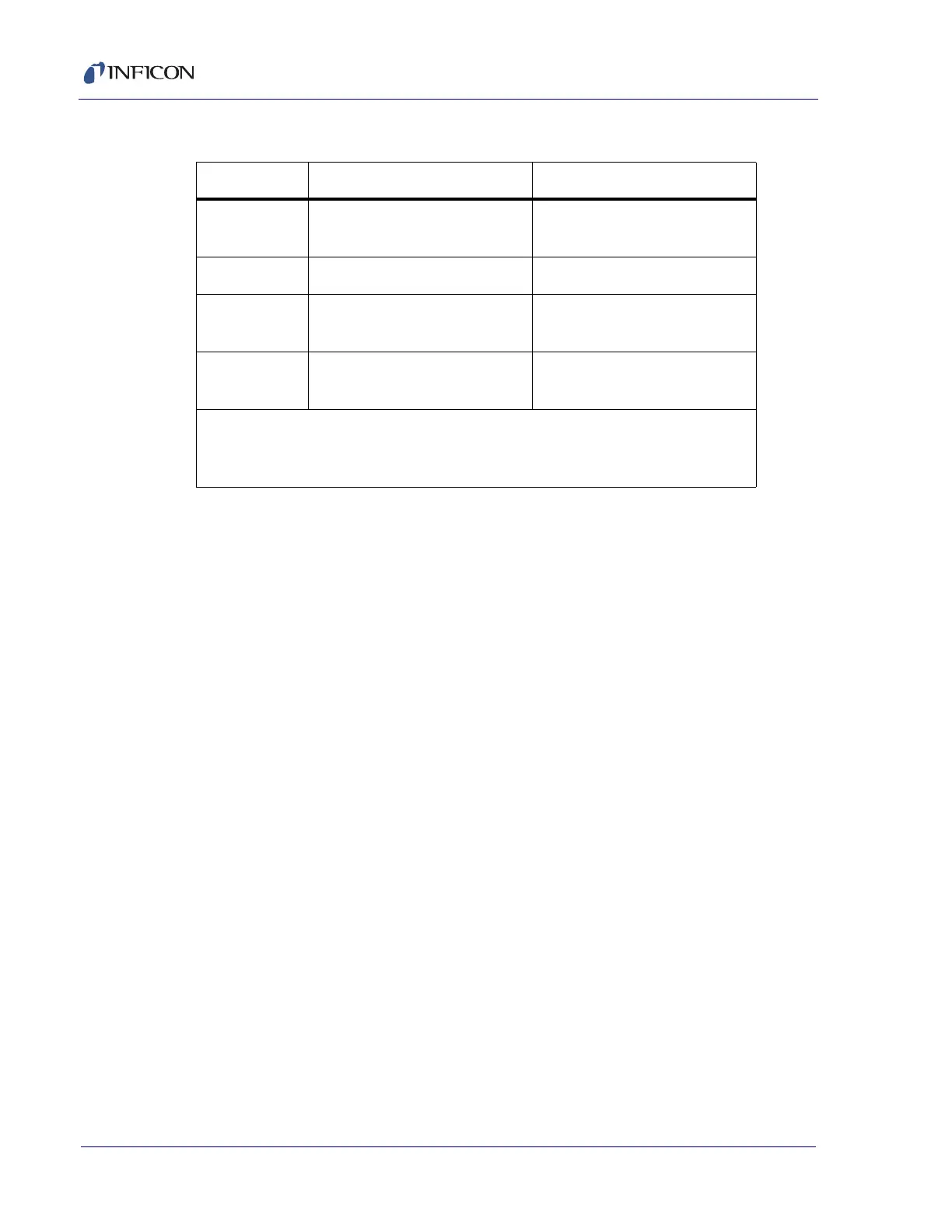
Table 5-8 Q40 command responses
Command XTC/3S Response XTC/3M Response
Q40 0 "a 0 0 " (a = 1 to 9,
0 = no film in layer)
"a b c" (a = 1 to 32, b = 0 to 32,
c = 0 to 32)
Q40 1 "a" (a = 1 to 9) "a" (a = 1 to 32)
Q40 2 "No Data" error "b" if b = 1 to 32
"No Data" error if b = 0
Q40 3 "No Data" error "c" if c = 1 to 32
"No Data" error if c= 0
a = Film # in Layer 1
b = Film # in Layer 2
c = Film # in Layer 3

Table of Contents

Questions and Answers:

Inficon XTC/3 Specifications

General IconGeneral
ModelXTC/3
Input Voltage100-240 VAC, 50/60 Hz
Operating Temperature0 to 50 °C
Rate Resolution0.01 Å/s
Measurement PrincipleQuartz Crystal Microbalance (QCM)
Power SupplyInternal
Communication InterfaceRS-232, Ethernet
DimensionsStandard 19" rack mount
WeightApprox. 5 kg
Crystal Sensor6 MHz Quartz Crystal
OutputsAnalog, Digital

Summary

Trademarks

Disclaimer

Copyright

Declaration Of Conformity

Warranty

Chapter 1 Introduction and Specifications

1.1 Introduction

Introduces the XTC/3 controller, its versions, and basic operation principles.

1.1.1 Related Manuals

Lists related manuals for sensors and accessories.

1.2 XTC/3 Safety

Covers safety definitions, general information, and specific warnings related to electrical hazards.

1.2.1 Definition of Notes, Cautions and Warnings

1.2.2 General Safety Information

1.2.3 Earth Ground

1.2.4 Main Power Connection

1.3 How to Contact INFICON

1.3.1 Returning Sensor to INFICON

Provides instructions and requirements for returning sensor components to INFICON for service.

1.4 XTC/3 Specifications

1.4.1 Measurement

Details the measurement specifications, including frequency range, resolution, accuracy, and technique.

1.4.2 Screens and Parameters

Describes the navigation structure and the dedicated screens for monitoring and programming parameters.

1.4.3 Process Recipe Storage

Outlines the storage capacity for process and film programs for XTC/3M and XTC/3S.

1.4.3.1 Film Parameters

Lists and defines parameters for Pre/Post Deposit and Deposit stages, including ramps, levels, times, and rates.

1.4.4 Display

Specifies the display type, format, resolution, and ranges for thickness and rate.

1.4.5 Source / Recorder Outputs

Details the quantity, configuration, function ranges, and resolution of source and recorder outputs.

1.4.6 Relays / Inputs

Describes the ratings and types of relays and inputs available on the controller.

1.4.7 Remote Communications

Lists communication interfaces like RS232 and Ethernet TCP/IP with their configurations.

1.4.8 Accessories

Lists available accessories such as handheld controllers, kits, and software.

1.4.9 Power

Specifies power requirements, apparent power, fuse rating, and temporary overvoltages.

1.4.10 Operating Environment

Defines usage, temperature, humidity, altitude, installation, measurement, and pollution degree specifications.

1.4.11 Storage Temperature

Specifies the acceptable temperature range for storing the unit.

1.4.12 Warm Up Period

States that no warm-up is required but recommends a period for maximum stability.

1.4.13 Size

Provides the physical dimensions of the unit.

1.4.14 Connector Clearance Requirements

Specifies the required clearance around front and rear connectors.

1.4.15 Weight

States the weight of the unit with all options.

1.4.16 Cleaning

Provides instructions for cleaning the unit using mild cleaners.

1.5 Unpacking and Inspection

1.6 Parts and Options Overview

Lists available base configurations for XTC/3M and XTC/3S control units, including part numbers.

1.6.1 Base Configurations

Lists the available base configurations for XTC/3M and XTC/3S control units, including part numbers.

1.6.2 Accessories

Lists various oscillator kits, sensor emulator kits, and software accessories with their part numbers.

1.6.3 Replacement Cables & Oscillators

Lists part numbers for replacement cables and oscillators for interfacing with the controller.

1.6.4 Sensors

Lists INFICON sensor types compatible with the XTC/3 controller.

1.7 Initial Power On Verification

Chapter 2 Installation and Interfaces

2.1 Location Guidelines

Provides recommendations for installing the XTC/3 for optimal performance and longevity.

2.1.1 Sensor Types

Discusses sensor types dictated by process needs and general guidelines from INFICON.

2.1.2 Sensor Installation

Illustrates and guides typical installation of INFICON water-cooled crystal sensors in vacuum chambers.

2.1.3 XTC/3 Installation

Describes rack mounting and table-top installation options for the controller.

2.2 Avoiding Electrical Interference

Emphasizes electrical guidelines to prevent noise issues and ensure safe operation.

2.2.1 Verifying/Establishing Earth Ground

Recommends procedures for establishing a proper earth ground connection.

2.2.2 Connections to Earth Ground

Details the two earth connections required for the controller and associated warnings.

2.2.3 Minimizing Noise Pickup from External Cabling

Provides guidelines for routing cables to minimize noise pickup and ensure proper shielding.

2.3 Connecting the Controller

Outlines the process of connecting the controller to power and signal interfaces.

2.3.1 Verifying the Correct Input Voltage

Details warnings and requirements for verifying the correct input voltage before connecting power.

2.3.2 Routing Oscillator (XIU) Cables

Advises on routing oscillator cables to avoid electromagnetic interference.

2.3.3 Interface Cable Fabrication and Pin-Out

Notes the need to fabricate interface cables and refers to noise minimization guidelines.

2.3.3.1 Source Control Connection

Describes the BNC connectors for source control voltage and the use of coaxial cables.

2.3.3.2 Input and Output Connections

Provides caution regarding voltage and current ratings for I/O connectors and relays.

2.3.3.2.1 System I/O Connector

Details the pin assignments and functions for the system I/O connector, including tables for standard and film select options.

2.3.3.2.2 Aux I/O Connector

Lists the pin assignments and functions for the auxiliary I/O connector, detailing relays and TTL outputs.

2.3.3.2.3 Inputs

Explains how inputs are activated and their characteristics, including activation by contact closure or TTL/CMOS logic.

2.3.4 RS-232C Communications

Explains the use of RS-232C for remote control and monitoring, including software and cable requirements.

2.3.5 TCP/IP Communications Connection (Optional)

Discusses the optional TCP/IP interface for Ethernet communications, including cable type and addressing.

Chapter 3 Operation

3.1 Front Panel Controls

Identifies and describes the functions of the front panel components, including system switches, LCD screen, data entry keys, and cursor keys.

3.2 Rear Panel Interfaces

Identifies and describes the interfaces located on the rear panel of the XTC/3 controller.

3.3 Displays

Lists the seven display screens used for monitoring and programming processes and explains display dimming features.

3.3.1 Menu Display

Explains how to navigate through the XTC/3 screens using the MENU key and cursor keys.

3.3.2 Operate Display

Describes the Operate screen, which displays active film and process information upon power-up.

Operate Display Description

Provides a detailed breakdown of the information displayed on the Operate screen, referencing figures.

3.3.2.1 Crystal Life and Starting Frequency

Explains how crystal life is displayed and its use as an indicator for crystal replacement.

3.3.2.2 Choosing The Right Crystal

Provides recommendations for selecting gold or silver crystals based on application needs.

3.3.2.3 Percent Life Auto-Zero

Explains the auto-zero function for crystal life percentage and its implications.

3.3.3 Film Name Display

Shows the film parameters and values, and how to access Pre/Post Deposit, Deposit, Sensor, Source, and Option screens.

3.3.4 Process List Display (XTC/3M only)

Describes the Process screen for XTC/3M, which lists programmed processes and layers, and how to navigate and delete films.

3.3.5 General Parameter Display

Details the General parameter screen, subdivided into Process, Hardware, and Communication Info screens.

3.3.6 I/O Map Display

Explains the I/O Map screen, showing programmable I/O functions or fixed I/O.

3.3.7 Diagnostics Display

Describes the Diagnostics display, which shows firmware version, serial numbers, and allows testing of interfaces and components.

3.3.8 Sensor Information Display

Shows typical sensor information, including active sensor, frequency, type, and crystal life, and options for switching crystals.

3.4 Executing a Process

Explains how to start, stop, and reset a process, and suggests using TEST mode for verification.

3.5 State Descriptions

Defines pre-deposit states like READY and CRUCIBLE SWITCH, along with their conditions and relay contact status.

3.5.1 Alarms and Stops

Explains how unusual situations are detected as ALARMS or STOPS, and the difference between them.

3.5.1.1 Alarms

Lists conditions considered ALARMS by XTC/3, which result in ALARM relay closure.

3.5.1.2 Stops

Lists actions or conditions that produce a STOP state, indicated by STOP message and relay closure.

3.5.1.3 Recovering from STOP

Describes how to complete an interrupted process from a STOP state without reprogramming.

3.6 Special Features

Explains features like Autostart Next Layer, Ion Assisted Deposition, Control Delay, and Shutter Delay.

3.6.1 Automating a Process

Explains three methods to automate process execution, including Autostart Next Layer and remote controls.

3.6.2 Ion Assisted Deposition

Explains how the Ion Assist Output is activated when the film is in Deposit and the parameter is set to Yes.

3.6.3 Control Delay

Describes how Control Delay suspends the control loop to prevent response to temporary rate spikes.

3.6.4 Shutter Delay

Explains how Shutter Delay ensures no material deposition until rate requirements are met.

3.6.5 Rate Ramp Trigger of Final Thickness

Explains how to implement film termination using a rate ramp, and notes its exclusion in Time-Power state.

3.6.6 Transfer Sensor

Describes the Transfer Sensor function for rate control in Shutter Delay before Deposit.

3.6.7 Crucible Switching

Explains how crucible position output lines control evaporation sources and the Crucible Valid input.

3.6.7.1 Bin Mode

Describes Bin mode for sequential outputs, labeled Cruc Src 1 Bin and Cruc Src 2 Bin.

3.6.7.2 BCD Mode (XTC/3M only)

Describes BCD mode using sequential outputs for crucible selection, configured via I/O Map.

3.6.8 Crystal Switching

Details the choices of sensor types offering backup crystals and the requirements for CrystalTwo and Dual Head sensors.

3.6.8.1 CrystalTwo

Explains the CrystalTwo option requirements, wiring, and behavior during deposition and after layer completion.

3.6.8.2 CrystalSix

Describes how XTC/3 identifies and tracks CrystalSix positions and its automatic switching behavior during deposition.

3.6.8.3 Crystal12

Explains the Crystal12 sensor behavior on power-up, its verification process, and handling of Carousel Open and Xtal Fail messages.

3.6.8.4 Rotary Sensor Crystal Switching

Details how Rotary sensor type enables sequential switching for six positions and the fallback states if a good resonant frequency is not found.

3.6.8.5 Dual Head

Explains the Dual Head configuration, wiring, power-up initialization, and limitations like RateWatcher disablement.

3.6.8.6 XTC/3S Sensor Shutter / CrystalSwitch Output

Describes how Sensor Shutter outputs function as CrystalSwitch outputs in XTC/3S depending on Sensor Type.

3.6.9 Start Layer Without Backup Crystal Configuration

Explains the "Start Without Backup" option for multi-position sensors and its implications for layer startup.

3.6.10 RateWatcher

Explains how the RateWatcher feature automatically samples deposition rate and maintains source power for stable deposition.

3.6.11 Hand-held Controller (Option)

Describes the optional wired Hand-held Controller for manual control of power, crystal switching, and STOP commands.

3.6.12 Lock Code

Explains how to set, clear, or recover a Lock Code to prevent unauthorized parameter changes.

3.6.13 Parameter Clear

Describes how to clear user-programmed parameters to default values using the CLEAR key on power-up.

3.6.14 Datalog

Explains how the RS-232 port functions as a "send only" port for datalog output, detailing the data stream format.

3.6.15 TCP/IP

States that the optional TCP/IP interface provides commands via static IP address and does not support DHCP.

Chapter 4 XTC/3 Programming

4.1 Overview

Outlines the basic procedure for programming the XTC/3, including making sure it's in READY state and defining films and processes.

4.2 Film Set Up Overview

Explains how to access the film setup screens after pressing the MENU key.

4.2.1 Film Set Up

Details accessing the Film Parameter display and navigating through Pre/Post, Deposit, Sensor, Source, and Option screens.

4.2.2 Film Definition

Defines a film by parameters like sensor/source numbers, rates, thickness, and material properties, noting differences between XTC/3M and XTC/3S.

4.2.3 Film Definition Parameters

States that film parameters are entered in the Pre/Post, Deposit, Sensor, Source, and Option screens.

4.2.3.1 Pre/Post Deposition Parameters

Lists and defines parameters for Pre/Post Deposition, including Rise Time, Soak Power, and Soak Time for both stages.

4.2.3.2 Deposit

Details deposit parameters like Rate, Final Thickness, Thickness Set Point, New Rate, and Rate Ramp Time.

4.2.3.3 Sensor Parameters

Defines sensor parameters like Sensor #, Tooling, and Second Tooling, and their applicability.

4.2.3.4 Source Parameters

Defines source parameters such as Source number, Crucible selection, Control Gain, Time Constant, Dead Time, Maximum Power, Density, and Z-Ratio.

4.2.3.5 Option

Lists and defines optional film parameters like Time Power, Delay Option, Transfer Sensor, Transfer Tooling, Control Delay Time, Ion Assist Deposit, and Name.

4.3 Process Set-Up Overview (XTC/3M only)

Explains how to access the Process display in XTC/3M for programming processes and layers.

4.3.1 Process Definition

Details the Process screen for defining processes, including Process Number and Process Name.

4.4 General Parameters

Explains how to access the General Parameter display, which is subdivided into Process, Hardware, and Comm Info screens.

4.4.1 Process Parameters

Details the Process parameters for XTC/3M and XTC/3S, including Process to Run and Film to Run options.

4.4.2 Hardware Parameters

Covers hardware parameters such as Sensor Type, Source Control Voltage, Recorder Mode, Filter, Audio Feedback, and LCD Dimmer Time.

4.4.2.1 XTC/3S Film Select Option

Explains the Film Select option for XTC/3S, allowing film selection based on inputs and reassigning Input #4 for RESET.

4.4.3 Comm Info

Details the Comm Info screen for configuring RS-232 and TCP/IP interfaces, including baud rate, protocol, and IP address.

4.4.3.1 Remote Communication Parameters

Specifies RS-232 settings (Baud Rate, Protocol) and Ethernet Interface settings (IP Address, Net Mask).

4.5 I/O Overview

Explains how to access the I/O Map display to view programmable I/O functions or fixed I/O.

4.5.1 XTC/3S Inputs and Outputs

Describes the fixed I/O displayed on the XTC/3S I/O Map screen and refers to Film Select Option and previous sections for details.

4.5.2 XTC/3M Inputs

Explains the screen for modifying the 9 inputs in XTC/3M and how to assign input functions.

4.5.3 XTC/3M Outputs

Describes how to modify relay and TTL outputs in XTC/3M, including assigning functions and setting states.

4.5.4 Clear Input or Output

Explains how to clear input or output assignments by selecting <Blank> and entering the number.

Chapter 5 Remote Communications

5.1 Remote Communications Overview

Explains that XTC/3 can be remotely controlled, programmed, or interrogated using a remote command set.

5.1.1 Message Protocols

Describes the message protocol structure, including supported RS-232 protocols and the absence of hardware handshaking.

5.1.2 Physical Connections

Describes the two types of data communications hardware ports available: RS-232C and optional TCP/IP.

5.1.3 RS-232C Serial Port

Details the RS-232C serial port, including connector type, cable length, configuration, and limitations.

5.1.4 TCP/IP Ethernet Port

Explains TCP/IP communication, port number, binary commands, and addressing support.

5.1.4.1 Network Connection

Specifies the use of a standard straight Ethernet cable for network or hub connections.

5.1.4.2 How to Set Up the Network Protocol on the PC

Provides manual configuration steps for PC's IP address and subnet mask for direct communication with XTC/3.

5.2 Standard Protocol Message Format

Defines the message format used for Standard and TCP/IP protocols, including mnemonics.

5.2.1 Standard Protocol

Defines the key elements and structure of the standard protocol, including length, message, and command formats.

5.2.1.1 Standard Command Packet (Host to XTC/3 Message)

Details the format of standard command packets sent from a host to the XTC/3, including length, message structure, and command groups.

5.2.1.2 Standard Response Packet (XTC/3 to Host Message)

Details the format of standard response packets sent from the XTC/3 to a host, including length, CCB, timer, and response message structure.

5.2.2 Standard Communication Commands

Lists general definitions and specific communication commands like ECHO, HELLO, QUERY, UPDATE, STATUS, and REMOTE.

5.2.2.1 Standard ECHO Command

Defines the ECHO command for echoing messages back to the sender.

5.2.2.2 Standard HELLO Command

Defines the HELLO command to retrieve model and software version information.

5.2.2.3 Standard QUERY Commands

Introduces standard query commands used to retrieve parameter information.

5.2.2.3.1 Query Block

Defines the Query Block command (QB) for retrieving all parameters or specific subsets.

5.2.2.3.2 Standard Query Film Name (XTC3/M only)

Defines the command to query film names from the XTC/3M.

5.2.2.3.3 Standard Query Film Parameters

Defines the command to query film parameters, specifying Command ID and Film Number.

5.2.2.3.4 Standard Query General Parameter

Defines the command to query general parameters, specifying Command ID.

5.2.2.3.5 Standard Query Input Definition (XTC/3M Only)

Defines the command to query input definitions for XTC/3M, specifying Input Number.

5.2.2.3.6 Standard Query Output Definition (XTC/3M Only)

Defines the command to query output definitions for XTC/3M, specifying Output Number.

5.2.2.3.7 Standard Query Output Type Definition (XTC/3M Only)

Defines the command to query output type definitions for XTC/3M, specifying Output Number and Type.

5.2.2.3.8 Standard Query Process Parameters (XTC/3M Only)

Defines the command to query process parameters for XTC/3M, specifying Command ID, Process Number, and Parameter List.

5.2.2.4 Standard UPDATE Commands

Introduces standard commands for updating parameters.

5.2.2.4.1 Update Block

Defines the Update Block command for updating multiple parameters in a block.

5.2.2.4.2 Standard Update Film Name (XTC/3M only)

Defines the command to update film names for XTC/3M, specifying Film Number and Name.

5.2.2.4.3 Standard Update Film Parameters

Defines the command to update film parameters, specifying Command ID, Film Number, and Parameter Value.

5.2.2.4.4 Standard Update General Parameters

Defines the command to update general parameters, specifying Command ID and Parameter Value.

5.2.2.4.5 Standard Update Input Definition (XTC/3M only)

Defines the command to update input definitions for XTC/3M, specifying Input Number and Definition.

5.2.2.4.6 Standard Update Output Definition (XTC/3M only)

Defines the command to update output definitions for XTC/3M, specifying Output Number and Definition.

5.2.2.4.7 Standard Update Output Type Definition (XTC/3M Only)

Defines the command to update output type definitions for XTC/3M, specifying Output Number and Type.

5.2.2.4.8 Standard Update Process Parameters (XTC/3M only)

Defines the command to update process parameters for XTC/3M, specifying Command ID, Process Number, and Parameter List.

5.2.2.5 Standard STATUS Commands

Introduces standard commands for querying status information.

5.2.2.6 Standard REMOTE Commands

Introduces standard remote commands for controlling the unit, specifying command ID and action values.

5.3 XTC/2 Protocols

Describes XTC/2 protocols (ASCII-based) that are in effect when selected under RS-232 Protocol parameter.

5.3.1 Basic Command Structure

Lists the basic commands available via computer communications for XTC/2 protocols.

5.3.2 XTC/2 Serial Communication with Checksum

Details the protocol for XTC/2 serial communication when checksum is selected.

5.3.3 XTC/2 Serial Communications - No Checksum

Details the protocol for XTC/2 serial communication when no checksum is selected.

5.3.4 XTC/2 Error Codes

Lists error codes (A-G) and their corresponding descriptions for XTC/2.

5.3.5 XTC/2 Message Strings

Lists message strings for XTC/2 commands like ECHO, HELLO, and QUERY.

5.3.5.1 XTC/2 ECHO Command

Defines the ECHO command format for XTC/2.

5.3.5.2 XTC/2 HELLO Command

Defines the HELLO command format for XTC/2.

5.3.5.3 XTC/2 QUERY Command

Defines the QUERY command format for XTC/2.

5.3.5.4 XTC/2 UPDATE Command

Defines the UPDATE command format for XTC/2.

5.3.5.5 XTC/2 STATUS Command

Defines the STATUS command format for XTC/2, specifying status codes.

5.3.5.6 XTC/2 REMOTE Commands

Lists XTC/2 remote commands, their codes, functions, and descriptions.

5.3.5.7 XTC/2 Sample Host Programs

Provides sample host programs for XTC/2 communication.

5.3.5.7.1 XTC/2 Program Without Checksum

Presents a sample GWBASIC program for XTC/2 communication without checksum.

5.3.5.7.2 XTC/2 Program With Checksum

Presents a sample GWBASIC program for XTC/2 communication with checksum.

Chapter 6 Troubleshooting, Status and Error Messages

6.1 Status and Error Messages

Lists and explains status and error messages encountered during operation, categorized by type.

6.2 XTC/3 Diagnostics

Explains the initial diagnostics display showing firmware revision and serial numbers, and how to access test functions.

Output Set or Clear

Describes how to verify output operation by toggling active outputs.

Active XIU Test

Details how to initiate the XIU Self Test to check Crystal Interface Unit and related components.

RS-232 Loopback

Explains how to initiate the RS-232C COMM PORT self-test using a Loop Back connector.

6.3 Troubleshooting Guide

Introduces a guide to help diagnose and resolve issues with XTC/3 performance or operation.

6.3.1 Troubleshooting XTC/3

Provides a symptom/cause/remedy chart for common XTC/3 issues like power, locking up, parameter loss, and key failures.

6.3.2 Troubleshooting Transducers/Sensors

Discusses diagnosing sensor head problems using a DVM and the optional Crystal Sensor Emulator.

6.3.2.1 Verifying Crystal Switching and Rotation

Explains how to check active sensor function using the Sensor Information screen.

6.3.2.2 Verifying Sensor Shutter Operation

Describes how to exercise the shutter on Crystal Two or shuttered sensors using the Diagnostics screen.

6.3.3 Troubleshooting Computer Communications

Addresses troubleshooting computer communication issues, including cable connections, baud rates, and protocols.

6.3.3.1 TCP/IP Module LED Diagnostics

Explains the meaning of the LED indicators on the TCP/IP module for diagnosing network status and diagnostics.

6.4 Replacing the Crystal

Provides general cautions and a procedure for replacing crystals, noting exceptions for specific sensor types.

6.4.1 Front Load Single Sensors

Details the step-by-step procedure for replacing the crystal in Front Load Single sensors.

6.4.2 Shuttered Front Load Single and Front Load Dual Sensors

States no difference in crystal replacement between shuttered and non-shuttered sensors.

6.4.3 Cool Drawer Sensor

Provides a step-by-step procedure for replacing the crystal in Cool Drawer sensors.

6.4.4 Bakeable Sensor

Describes crystal replacement for Bakeable sensors, noting the cam assembly unlock procedure.

6.4.5 Sputtering Sensor

Provides instructions for replacing the crystal in a sputtering sensor, including special crystal usage.

6.4.6 Crystal Snatcher

Explains how to use the crystal snatcher for removing and reinserting the crystal retainer.

6.4.7 CrystalSix

Refers to the CrystalSix Operating Manual for specific instructions.

6.4.8 Crystal12

Refers to the Crystal12 Operating Manual for specific instructions.

6.5 Crystal Sensor Emulator PN 760-601-G2

Introduces the Crystal Sensor Emulator for diagnosing deposition controller measurement systems.

6.5.1 Diagnostic Procedures

Describes procedures using the emulator to analyze Crystal Fail messages.

6.5.1.1 Measurement System Diagnostic Procedure

Details steps to diagnose the measurement system using the emulator and BNC cable, checking for XTAL Fail messages.

6.5.1.2 Feed-Through Or In-Vacuum Cable Diagnostic Procedure

Provides diagnostic steps for the feed-through and in-vacuum cable using the emulator and Ohm meter.

6.5.1.3 Sensor Head Or Monitor Crystal Diagnostic Procedure

Details diagnostic steps for the sensor head or monitor crystal using the emulator and Ohm meter.

6.5.1.4 System Diagnostics Pass But Crystal Fail Message Remains

Outlines tasks to perform if the Crystal Fail message persists after diagnostics, including checking retainer and cover.

6.5.2 % XTAL Life

Explains the expected % XTAL Life display reading when using the Crystal Sensor Emulator.

6.5.3 Sensor Cover Connection

Discusses the compatibility of the Crystal Sensor Emulator's Sensor Cover Connector with different sensor heads.

6.5.3.1 Compatible Sensor Heads

Lists sensor heads compatible with the Crystal Sensor Emulator's Sensor Cover Connection.

6.5.3.2 Incompatible Sensor Heads

Lists sensor heads incompatible with the Crystal Sensor Emulator's Sensor Cover Connector.

6.5.4 Specifications

Lists the dimensions, temperature range, frequency, and materials of the Crystal Sensor Emulator.

Chapter 7 Calibration Procedures

7.1 Importance of Density, Tooling and Z-Ratio

Explains the importance of density, tooling, and Z-Ratio for accurate thickness measurement and calibration.

7.2 Determining Density

Provides steps to determine density value using a substrate and short deposition, referencing material library values.

7.3 Determining Tooling

Outlines steps to calculate the tooling factor using a test substrate, deposition, and a specific relationship.

7.4 Laboratory Determination of Z-Ratio

Explains how to calculate Z-Ratio from material properties and describes a direct method for precise calibration.

7.5 Estimating Z-Ratio

Provides rules for estimating Z-Ratio for multiple layer depositions based on relative layer thicknesses.

Chapter 8 Measurement and Control Theory

8.1 Basics

Explains the fundamental principles of quartz crystal microbalance (QCM) and its use in vacuum deposition.

8.1.1 Monitor Crystals

Describes the quartz resonator, its frequency response spectrum, and improvements in monitor crystal design.

8.1.2 Period Measurement Technique

Explains the period measurement technique using a second oscillator to determine crystal oscillation period.

8.1.3 Z-Match Technique

Describes the Z-Match equation developed by Lu and Lewis for real-time calculation of thickness.

8.1.4 Active Oscillator

Explains the active oscillator circuit used to keep the crystal in resonance and its stability characteristics.

8.1.5 ModeLock Oscillator

Introduces INFICON's ModeLock Oscillator technology for eliminating oscillator limitations and improving accuracy.

8.1.6 Control Loop Theory

Explains the instrumental advances in measurement and their translation into process control using PID models and tuning techniques.

Chapter A Material Table

Related product manuals