3 - 2
XTC/3 Operating Manual
5 Power
This switch controls secondary power to XTC/3 between ON and STANDBY.
Power is provided when the button is in its depressed position.
6 Pilot Light
A green LED, adjacent to the power switch, is illuminated when power is on.
7 Remote Control Jack
Receptacle for the optional wired handheld remote controller PN 755-262-G1.
8 Optional Rack Mount Kit (Not Shown)
PN 780-702-G1 for one XTC/3.
PN 780-702-G2 for two XTC/3 mounted side by side.
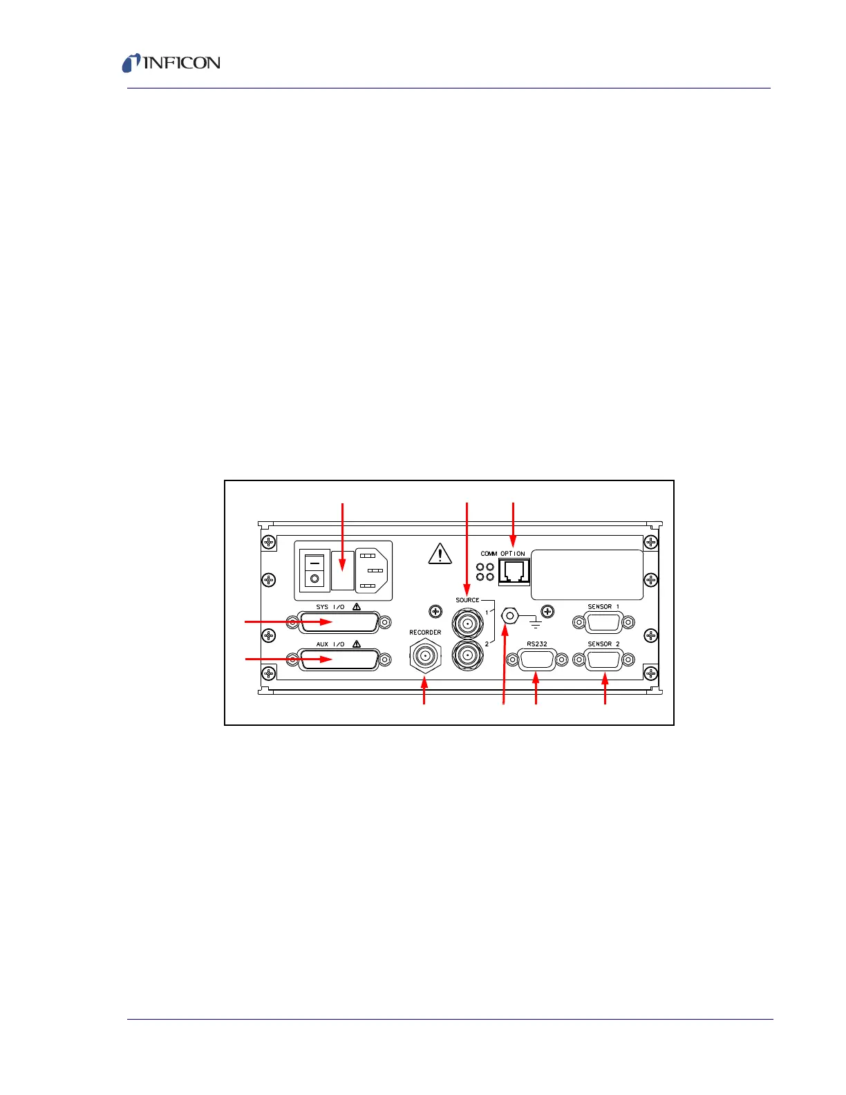
3.2 Rear Panel Interfaces
Interfaces for XTC/3 are located on the rear panel, see Figure 3-2.
Figure 3-2 XTC/3 rear panel
1 AC Power Inlet and Mains Switch
Provides a common connector for various international plug sets.
2 Source Control DAC Outputs
Provides source control voltage for two sources, (BNC connectors).
Outputs are programmable for various voltage ranges and polarities.
3 Comm Option Connector (Optional TCP/IP)
Provides connections for TCP/IP interface.
4 Sensor Connectors - Channels 1 & 2
Provides connection for the two sensor channels.