LP500 Series Service Manual 42
Assembly Notes
♦ Insert rear bezel into the bottom case first. The outside tabs on the rear bezel fit inside the bottom
case. Then lower the front of the chassis into place over the optical engine.
♦ Make sure to use the Plastite Torx screws in the rear. Torque them to 6 in-lbs (.68 Nm). Torque the
front Torx screws to 4 in.-lbs (.45 Nm).
♦ Make sure to connect the inline safety cable connector. If this cable is disconnected, the projector will
not generate a lamp enable signal.
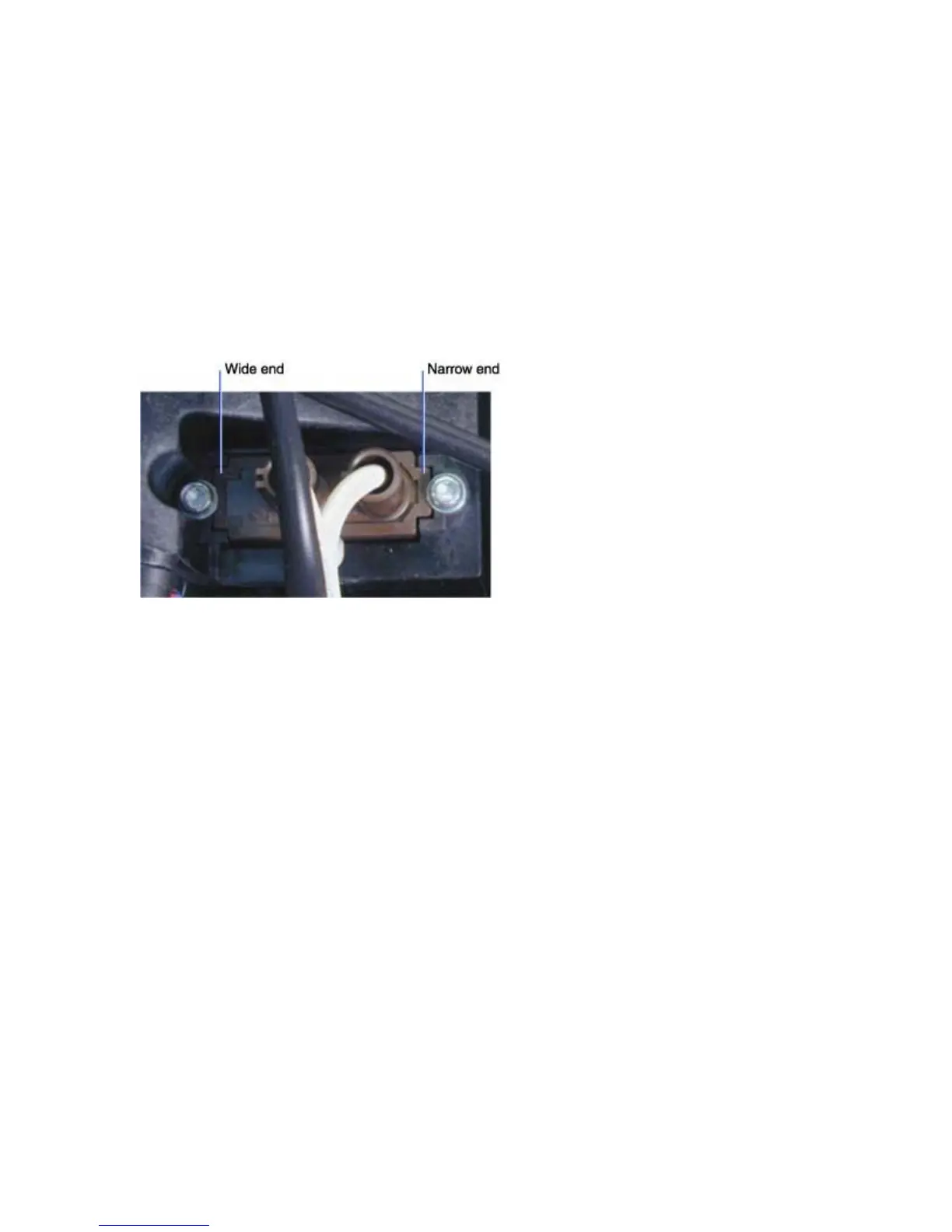
♦ Note that the lamp cable connector is keyed so that it fits into its hole in the lamp housing only one
way.