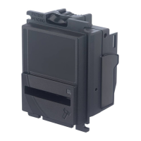
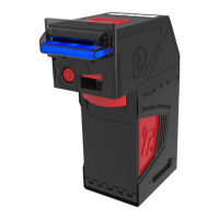
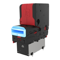
GA02118 User Manual BV20
<< Back to Contents
Copyright © Innovative Technology Ltd 2018 Doc: GA02118/1 User Manual BV20
Version: 1.0
Page 43 of 60
7 FIRST LEVEL SUPPORT
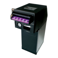
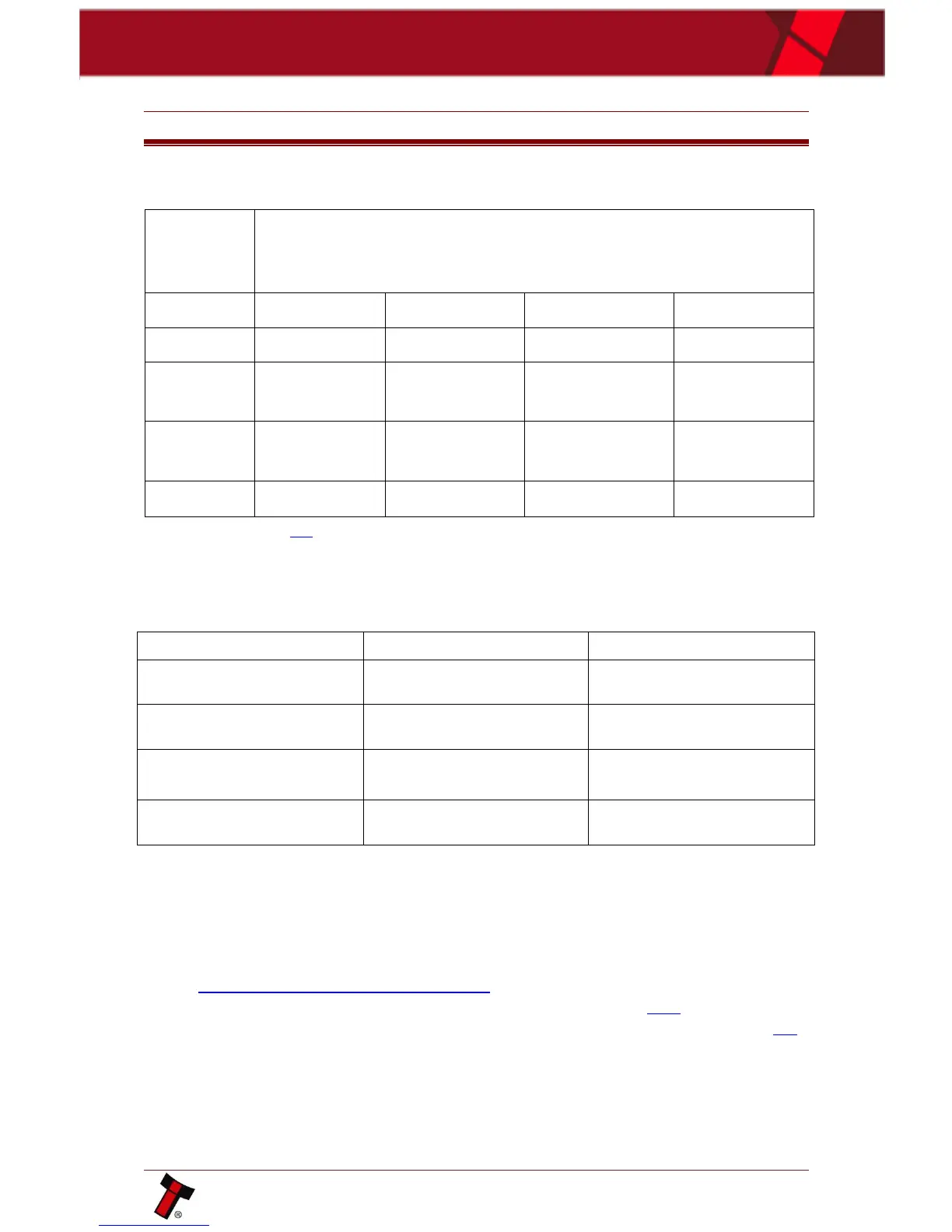
7.1 Bezel LED Flash Codes
The Bezel LED’s are used to indicate a variety of status signals as described below.
*- refer to section 8.4 for unit initializing.
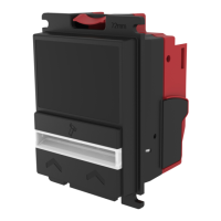
7.2 Configuration Button Functions
The BV20 has Configuration Button, which allows to perform several functions:
Sets BV20 to Programming
Mode (SSP protocol)
Enables Configuration Card
Programming Mode
Press Twice (within half a
second)
Current Setting Indicator
Press and hold as power is
applied
Resets ccTalk key to Default
setting
7.3 Checking Power and Communication Connections
1. Connect BV20 via TTL-USB adapters, either IF-17 or DA2 should be used. ITL
provides principal electrical scheme of IF-17 adapter, please contact
support@innovative-technology.co.uk for details.
2. Power supply parameters details are described in Section 10.4.
See also Bezel LED flash codes to identify any validator's errors in section 7.1.