Key RVP Features and Block Diagrams
User Guide Intel Confidential 19
• A cable is required to be connected to the header on the RVP and the other end of
this cable is a TypeC port.
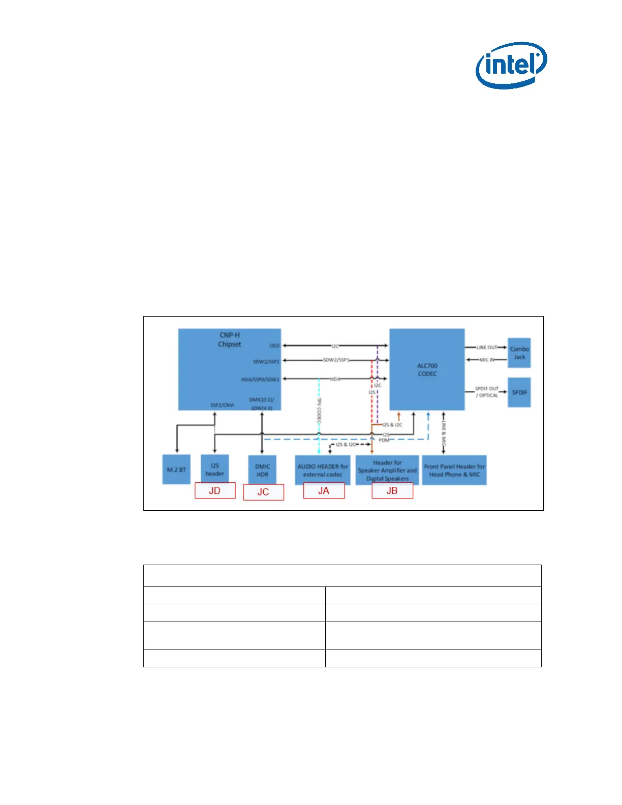
3.9 Audio Feature
• Default support for onboard codec is HDA mode.
• JA (Refdes J9A2) and JB (J9A3) is used for connecting to Speaker Amps and Digital
Speakers.
• JA is standard Azalia connector for connecting to external Codecs.
• JC (J9B1) for Connecting PDM microphones.
• JD (J9B5) for I2S2 interface.
• JE (J9B2) for SW Star Topology.
Figure 8. Block Diagram – Audio
3.10 I2C Mapping
LPSS I2C Mapping
LPSS I2C0(3.3V) PSS
LPSS I2C1(3.3V) Touch Panel
LPSS I2C2(muxed with SMLINK0 and ISH
UART0)(1.8V)
Onboard Sensor, Audio header, 2X3 header
LPSS I2C3(muxed with ISH I2C2)(1.8V) Type-C PD controller, 1X7 header




 To Next Page