Development Kit User’s Guide
October 2008 Order Number: 320067-002US
31
Technical Reference—Intel
®
EP80579 Integrated Processor with Intel
®
QuickAssist Technology
4.5 Fixed I/O Map and Interrupts
See the Intel
®
EP80579 Integrated Processor Product Line Platform Design Guide for
information about fixed I/O maps and interrupts.
4.6 Jumper Block
Figure 12 shows the location of the jumper blocks. Table 13 lists the settings and usage
of the jumpers. Review Figure 12 and Table 13 before changing the default jumper
settings.
Warning: Do not move jumpers when the power is on. Always turn off the power and unplug the
power cord from the power supply before changing a jumper setting. Otherwise, the
Intel
®
EP80579 Integrated Processor may be damaged.
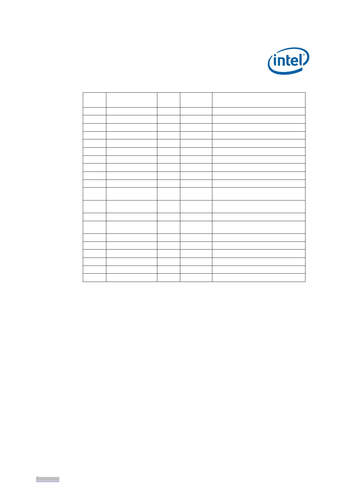
F 1.8V DS9K1 Green 1.8V LED
G 1.8V DDR DS8B1 Green 1.8V DDR LED
H 2.5V DS9F1 Green 2.5V LED
I 3.3V CR3G1 Green 3.3V LED
J5.0V CR4G1Green5V LED
K 5.0V Standby CR4G2 Green 5V standby LED
L CPU_RESET# DS4E3 Red Processor reset
M CPU_THERMTRIP# DS4F3 Red Processor Thermtrip triggered
N CPU_PROCHOT DS4F2 Red Processor PROC_HOT signal triggered
O IMCH_CPUSLP DS4E1 Red Processor entering sleep state
P IMCH_SUS_STAT DS4D1 Red
Suspend status. System entering a low
power state.
QIMCH_STPCLK DS4F1Red
Suspend Clock: output clock from RTC
generator circuit to use as a refresh clock.
R PEX_FATAL_ERR DS2D1 Red Error in PCIe switch
S IERR DS4E2 Red
Processor encountered an error. May
require a reboot.
T SLP_S3# DS5E1 Green Sleep S3
U INIT33V DS1J1 Red Firmware Hub Init
V SATA LED DS3J1 Green SATA hard drive activity status
W WDT_Timer_Out CR3H1 Green Watchdog timer expired
X SIO_LED_GRN DS2G2 Green General purpose LED for SIO
Y SIO_LED_YLW DS2G1 Yellow General purpose LED for SIO
Table 12. Signal and Voltage LED Indicators (Sheet 2 of 2)
Call-out Signal
Label
Name
LED Color Description