Development Kit User’s Guide
October 2008 Order Number: 320067-002US
43
Technical Reference—Intel
®
EP80579 Integrated Processor with Intel
®
QuickAssist Technology
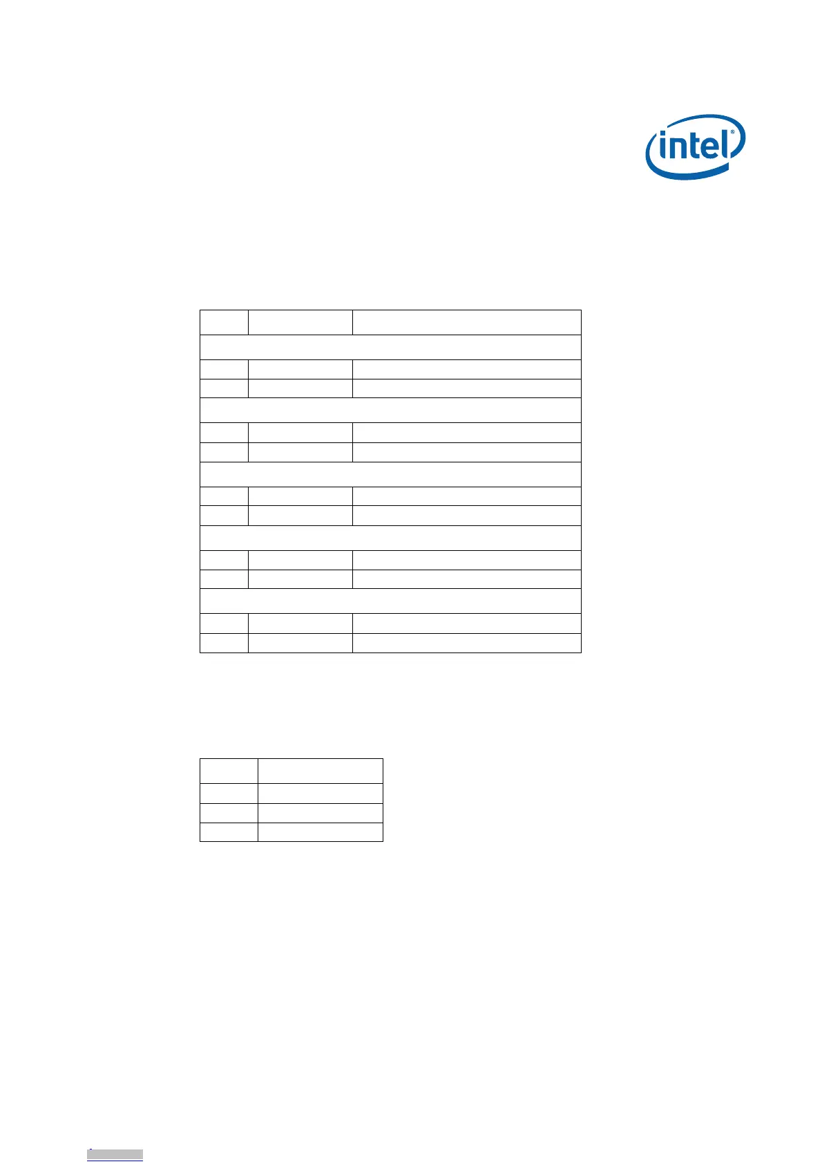
4.8.7 Front Panel Header
The Intel
®
EP80579 Development Board has a 10-pin keyed header for the front panel
connector. This section describes the functions of the front panel header. Table 23
shows the pinout.
4.8.8 SMBus Header
The Intel
®
EP80579 Development Board provides four external headers to support
access to the SMBus. For the SMBus header pinout, refer to Table 24.
Table 23. Front Panel Header Pinout
Pin Signal Description
Hard Drive Activity LED
1 HD_ACT_LED_P Hard drive activity LED +
2 HD_ACT_LED_N Hard drive activity LED -
Power LED
3 FP_PWR_LED_P Power LED +
4 FP_PWR_LED_N Power LED -
Power On/Off Switch
5 GND Ground
6 FP_PWR_BTN_N Power on/off switch
Reset Switch
7 FP_Reset_BTN_N Power reset switch
8 GND Ground
Others
9 GND Ground
10 Key (no pin) Key (unconnected)
Table 24. SMBus Header Pinout
Pin Signal
1Data
2 Ground
3Clock